Thick steel plate with excellent low temperature toughness

A kind of thick steel plate, extremely low temperature technology, applied in the field of thick steel plate

Inactive Publication Date: 2017-11-14
KOBE STEEL LTD
View PDF7 Cites 0 Cited by
  • Summary
  • Abstract
  • Description
  • Claims
  • Application Information

AI Technical Summary

Problems solved by technology

However, no technology has been proposed to satisfy the above-mentioned requirements for the brittle fracture ratio in high-strength thick steel plates with high base material strength as described above.

Method used


Image

  • Thick steel plate with excellent low temperature toughness
  • Thick steel plate with excellent low temperature toughness
  • Thick steel plate with excellent low temperature toughness

Examples


Embodiment 1

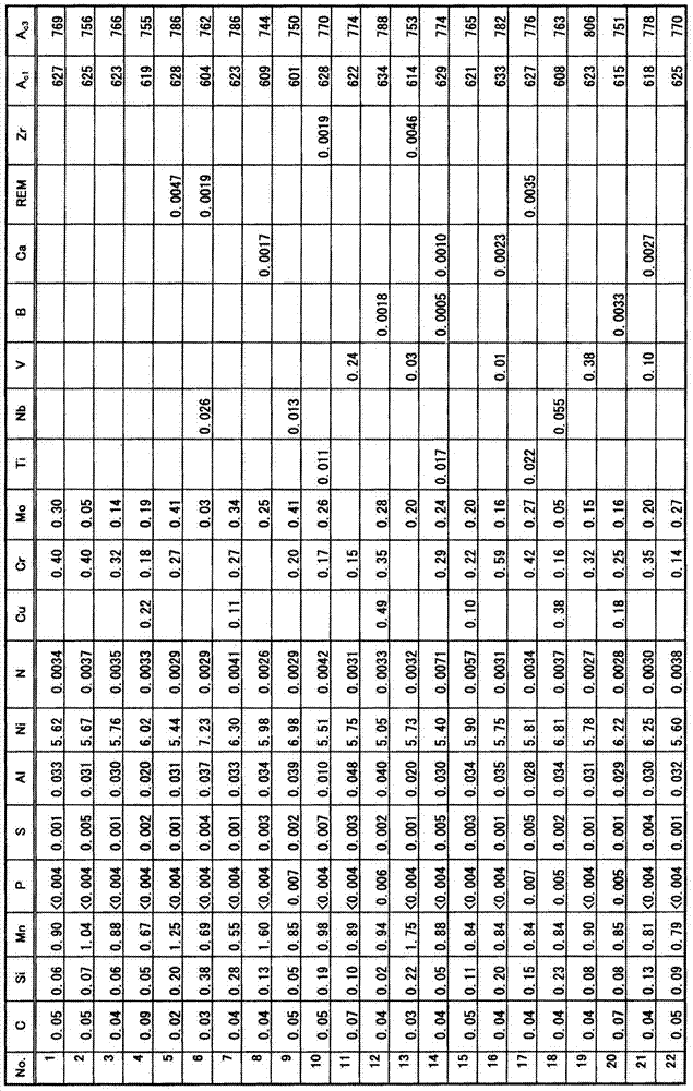
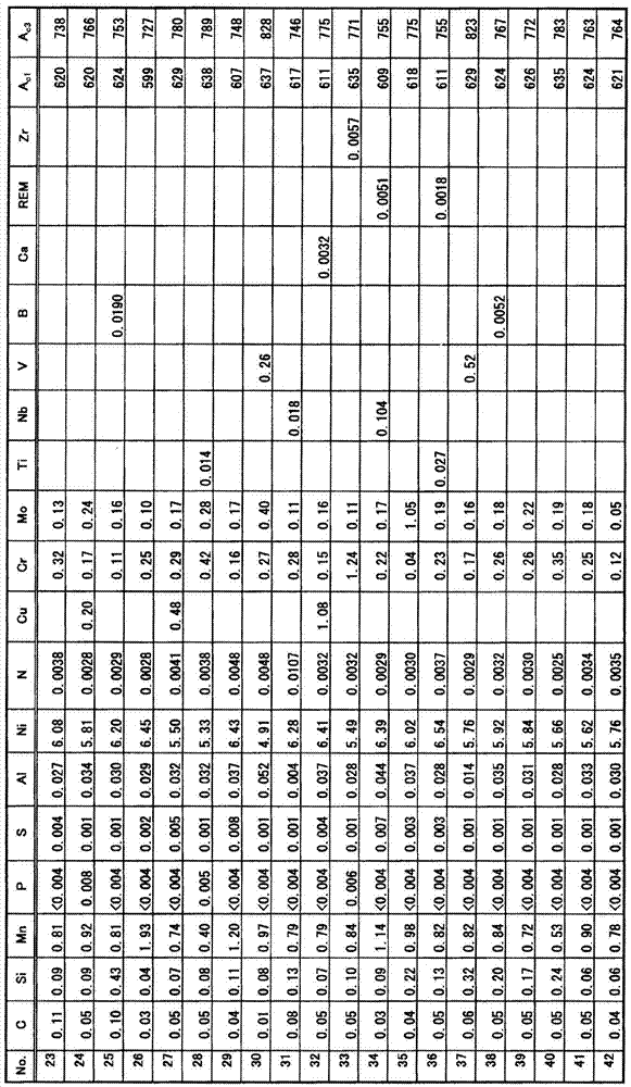
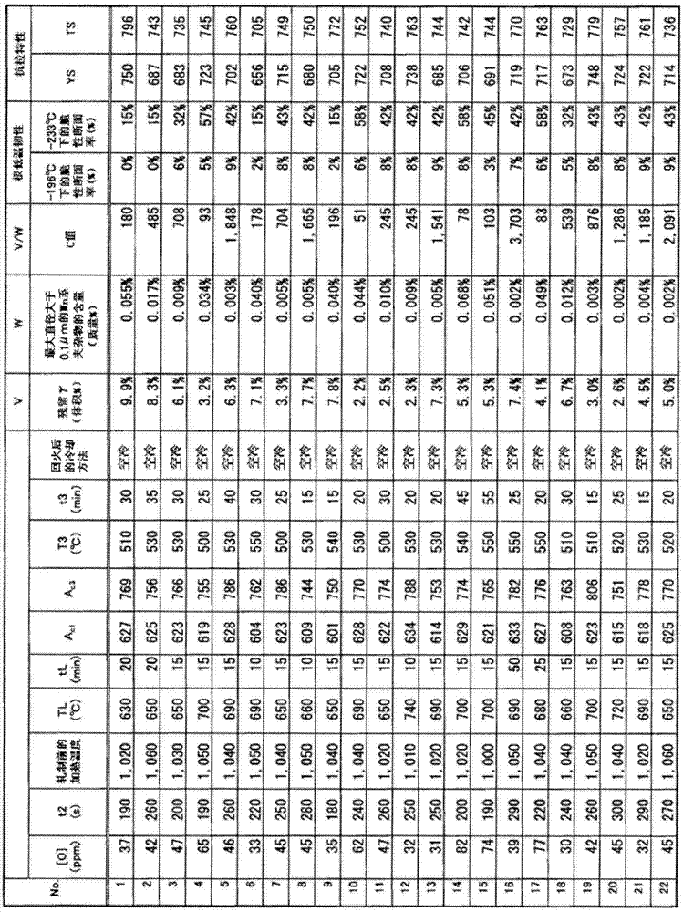
[0116] Use vacuum melting furnace (150kgVIF), with the smelting condition shown in table 2, smelt the test steel of composition shown in table 1 (remainder: iron and unavoidable impurity, unit is mass %), after casting, by heat Forging to make steel ingots of 150mm×150mm×600mm. In this embodiment, as the REM, a mixed rare earth metal containing about 50% of Ce and about 25% of La is used. In addition, the order of adding deoxidizing elements is Si, Mn (simultaneously added)→Al when optional components are not contained; on the other hand, when optional components containing Ti, REM, Zr, and Ca are contained, Si, Mn (simultaneously added) →Al→Ti→REM, Zr, Ca (simultaneously added). In addition, in Table 2, [O] is the amount of dissolved oxygen (ppm) before adding Al, and t2 is the cooling time (seconds) at 1500 to 1450° C. during casting. Cooling at 1500-1450°C is controlled by air cooling or water cooling so as to achieve the above-mentioned cooling time.

[0117] Next, the ...


PUM

PropertyMeasurementUnit
tensile strengthaaaaaaaaaa
yield strengthaaaaaaaaaa
thicknessaaaaaaaaaa

Abstract

The thick steel plate of the present invention contains predetermined steel components, the content of Mn-based inclusions with a maximum diameter greater than 0.1 μm in the steel is 0.001 to 0.07% by mass, and the fraction of the retained austenite phase that exists at -196°C is 2.0 to 12.0% by volume is satisfied.

Description

technical field [0001] The present invention relates to a thick steel plate excellent in ultra-low temperature toughness. Specifically, even if the Ni content is reduced to about 5.0 to 7.5%. ] Still good thick steel plate. The following description will focus on the above-mentioned thick steel plate for liquefied natural gas (LNG) exposed to extremely low temperatures (representatively storage tanks, transport ships, etc.), but the thick steel plate of the present invention is not intended to be limited thereto. , but can be fully applied to thick steel plates used in applications exposed to extremely low temperatures below -196°C. Background technique [0002] Thick steel plates for LNG tanks used for storage tanks for liquefied natural gas (LNG) require not only high strength but also high toughness that can withstand extremely low temperatures of -196°C. So far, thick steel plates containing about 9% of Ni (9% Ni steel) have been used as thick steel plates for the abov...

Claims


Application Information

Patent Timeline
Patent Type & Authority Patents(China)
IPC IPC(8): C22C38/00C22C38/40C22C38/58B22D11/124C21D8/02
CPCC22C38/00C21D9/46C21D2211/001C21D2211/004C22C38/001C22C38/002C22C38/005C22C38/02C22C38/04C22C38/06C22C38/08C22C38/12C22C38/14C22C38/16C22C38/18C22C38/42C22C38/44C22C38/46C22C38/48C22C38/50C22C38/54C22C38/58
Inventor 伊庭野朗名古秀德
Owner KOBE STEEL LTD
Why Eureka
Try Eureka