Eureka AIR delivers breakthrough ideas for toughest innovation challenges, trusted by R&D personnel around the world.

Vertical pneumatic fender

An inflatable fender technology, applied in climate change adaptation, water conservancy projects, ships, etc., can solve the problems of excessive air, bursting, discharge, etc., and achieve the effect of improving energy absorption performance

Inactive Publication Date: 2015-11-25
YOKOHAMA RUBBER CO LTD
View PDF12 Cites 6 Cited by
  • Summary
  • Abstract
  • Description
  • Claims
  • Application Information

AI Technical Summary

Problems solved by technology

At this time, if the safety valve is kept open, the air will be excessively exhausted to the outside, and in the worst case, the fenders will sink due to insufficient buoyancy
On the other hand, if the compression speed of the fenders is too fast relative to the discharge speed of the air to the outside, the internal pressure of the fenders will rise sharply, and in the worst case, there is a risk of bursting

Method used


Image

  • Vertical pneumatic fender
  • Vertical pneumatic fender
  • Vertical pneumatic fender

Examples


Embodiment Construction

[0024] Next, the vertical pneumatic fender of the present invention will be described based on the illustrated embodiment.

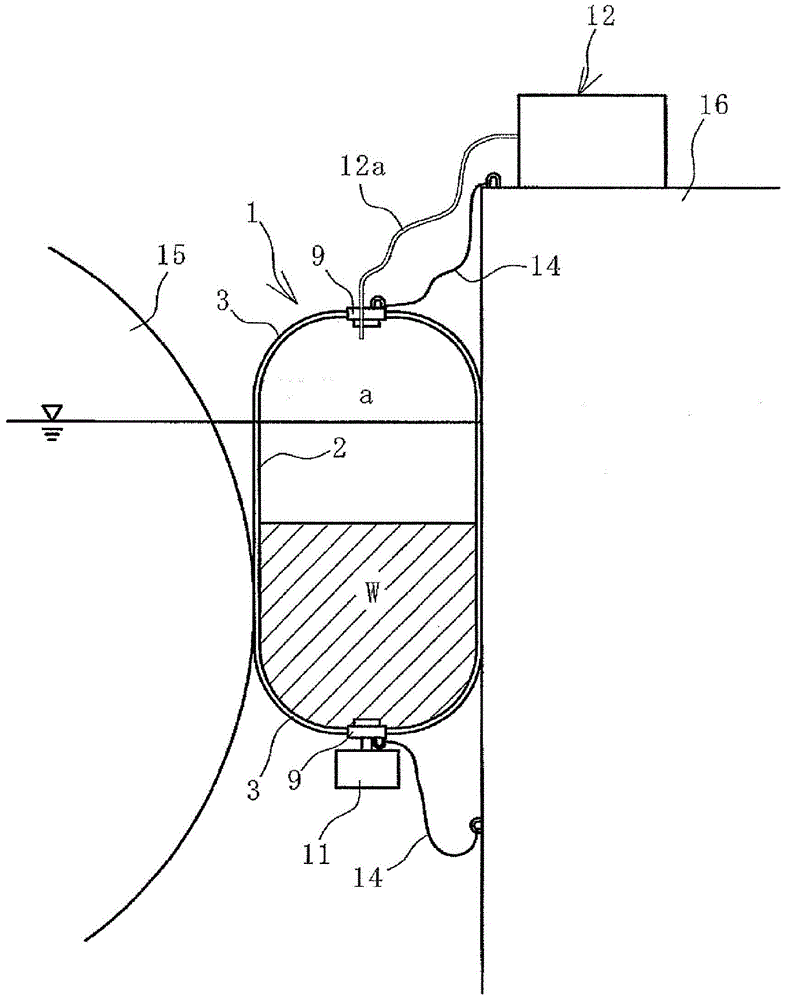
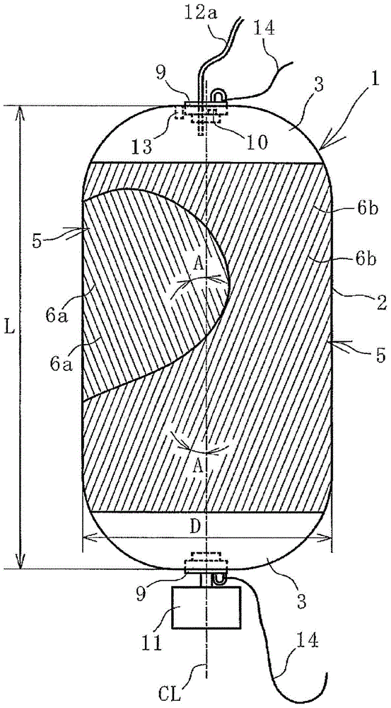
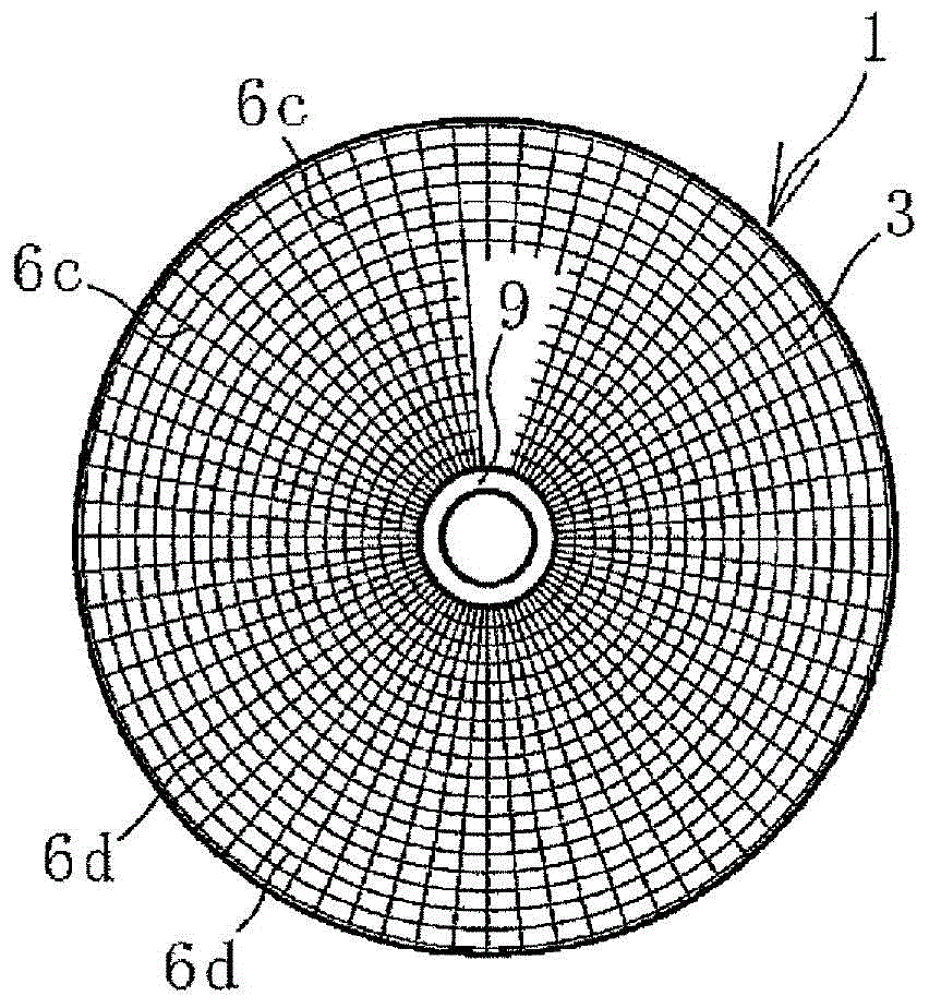
[0025] Such as Figure 1 ~ Figure 3 As shown, a vertical inflatable fender 1 of the present invention, hereinafter referred to as a fender 1 , is provided with bowl-shaped mirror portions 3 at both ends of a cylindrical trunk portion 2 . A cover portion 9 is provided on each mirror portion 3 . A predetermined amount of ballast water W is accommodated in the internal space of the fender 1 .

[0026] A safety valve 10 is provided on the cover part 9 of the upper mirror part 3 , and a pressure sensor 13 is provided on the cover part 9 or its surroundings. When the internal pressure of the fender 1 exceeds a preset upper limit pressure, the safety valve 10 is opened to discharge the air a in the internal space to the outside to reduce the internal pressure. The pressure sensor 13 is used to detect the internal pressure of the fender 1 .

[0027] An injec...


PUM


Abstract

Provided is a vertical pneumatic fender capable of handling a sudden increase in berthing energy. A heavy bob (11) is connected to a lower mirror (3), a prescribed amount of ballast water (W) is contained in an interior space, a trunk part (2) is configured with a plurality of reinforcing layers (5) laminated between an inner rubber layer (4) and an outer rubber layer (7), cords (6a, 6b) of laminated and vertically adjacent reinforcing layers (5) intersect each other and are disposed at a prescribed cord angle (A) in relation to the axial direction of a cylinder, an intermediate rubber layer (8) is interposed between each two reinforcing layers (5), and the cord angle (A) is set at 15-45° in a neutral state, whereby when additional air (a) is injected into the interior space of the fender (1) from an air injection apparatus (12) through an injection tube (12a), the cord angle (A) increases to an angle of repose while the intermediate rubber layer (8) undergoes shearing deformation, the trunk part (2) enlarges and expands, and the energy absorption capability of the fender (1) rapidly increases.

Description

technical field [0001] The present invention relates to a vertical inflatable fender, and in more detail, relates to a vertical inflatable fender capable of coping with a sharp increase in berthing energy. Background technique [0002] Among the pneumatic fenders, there is a vertical type pneumatic fender in which a weight is connected to the lower mirror part and a predetermined amount of ballast water is accommodated in the inner space. For example, refer to Patent Document 1. Vertical inflatable fenders maintain a stable posture by balancing the vertical downward force of the weight and ballast water contained in the interior space with the buoyancy of the fenders. [0003] Pneumatic fenders generally have bowl-shaped mirrors at both ends of a cylindrical body, and the body is formed by laminating multiple reinforcement layers between an inner layer of rubber and an outer layer of rubber. The reinforcing layer is a cord layer formed by aligning a plurality of cords in pa...

Claims


Application Information

Patent Timeline
Patent Type & Authority Applications(China)
IPC IPC(8): E02B3/26
CPCE02B3/26E02B17/003B63B59/02B63B2059/025Y02A30/30
Inventor 榊原繁树和泉南山田周家本晃宏
Owner YOKOHAMA RUBBER CO LTD
Why Eureka
Eureka Blog
Learn More