Drawing fluid spraying pipe for drawbench

The technology of drawing liquid and spraying pipe is applied in the field of drawing liquid spraying pipe for wire drawing machine, which can solve the problems of insufficient lubrication of metal wires and the like, and achieve the effects of increasing pressure, increasing cooling rate, and increasing spraying rate.

Inactive Publication Date: 2015-12-02
ANHUI YUSHENG HAOHAN ELECTRONICS TECH
View PDF7 Cites 2 Cited by
  • Summary
  • Abstract
  • Description
  • Claims
  • Application Information

AI Technical Summary

Problems solved by technology

When the metal wire passes through the mold hole, under the strong shaping of the mold hole, the metal wire is thinned and heated under the action of mechanical extrusion force. In order to cool down the metal wire and lubricate the metal wire, it is necessary to Install the lubricating device, and generally use a pipe with a round hole to spray the drawing liquid. When the drawing liquid is spilled from the liquid spray pipe, the drawing liquid will flow down the round hole, but the drawing liquid can only be aligned with the metal wire under the round hole. For lubrication, when the wire is deflected on the cone pulley, the wire drawing fluid cannot sufficiently lubricate the wire

Method used


Image

  • Drawing fluid spraying pipe for drawbench
  • Drawing fluid spraying pipe for drawbench

Examples


Embodiment Construction

[0011] In order to make it easy to understand the technical means, creative features, objectives and effects achieved by the present invention, the present invention will be further explained below in conjunction with specific drawings.

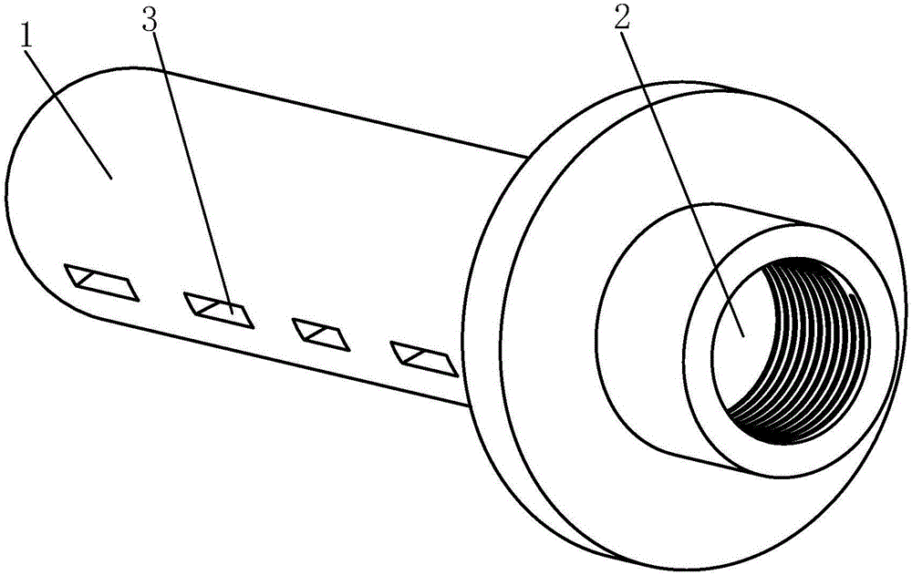
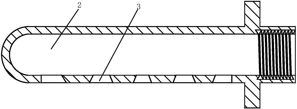
[0012] Such as Figure 1 to Figure 2 As shown, a drawing liquid spraying pipe for a wire drawing machine includes a pipe body 1, one end of the pipe body 1 is a cavity 2, and the lower end of the cavity 2 is provided with a plurality of water outlet holes 3 with a horizontal cross section. The left end surface of the leftmost water outlet hole 3 is a vertical surface, and the right end surface of the water outlet hole is an obtuse angle with the horizontal plane. The right end surface of the rightmost outlet hole 3 is a vertical surface, and the left end surface of the outlet hole is an inclined surface at an acute angle to the horizontal plane, and the left end surfaces of the remaining outlet holes 3 are all inclined surfaces at an acute angle...


PUM


Abstract

The invention relates to a drawing fluid spraying pipe for a drawbench. The drawing fluid spraying pipe for the drawbench comprises a pipe body. One end of the pipe body is provided with a cavity. A plurality of water outlets with rectangular horizontal sections are formed in the lower end of the cavity. The left end surface of the water outlet in the leftmost side is a vertical surface, and the right end surface of the water outlet in the leftmost side is an inclined surface at an obtuse angle relative to the horizontal plane. The right end surface of the water outlet in the rightmost side is a vertical surface, and the left end surface of the water outlet in the rightmost side is an inclined surface at an acute angle relative to the horizontal plane. The left end surfaces of the other water outlets are all inclined surfaces at acute angles relative to the horizontal plane, and the right end surfaces of the other water outlets are all inclined surfaces at obtuse angles relative to the horizontal plane. The spraying direction of drawing fluid flowing out of the water outlets is controlled through changes of the angles of the side edges of the water outlets, the drawing fluid is made to be in a water curtain shape along the cross section, and therefore the drawing fluid is sufficiently and evenly spayed on metal wires in any positions. Compared with a pipe simply provided with a strip-shaped groove, the strength of the spraying pipe is improved in the position with a through hole, the spraying pressure intensity of the drawing fluid is improved, and therefore the spraying speed of the drawing fluid is increased.

Description

Technical field [0001] The invention relates to the technical field of equipment for wire drawing machines, in particular to a wire drawing liquid spray pipe for wire drawing machines. Background technique [0002] Wire drawing machine is also called wire drawing machine. The English name of wire drawing machine is drawing machine. It is a widely used mechanical equipment in industrial applications. It is widely used in machinery manufacturing, hardware processing, petrochemical, plastic, bamboo and wood products, wire and cable industries. [0003] The wire drawing principle of the wire drawing machine is to use multiple mold holes to match the same number of tower wheels corresponding to the mold holes to gradually draw the larger diameter metal wire into the smaller diameter metal wire. The order of the mold holes is that of the mold holes. The inner diameter gradually decreases. When the metal wire passes through the mold hole, under the strong shaping of the mold hole, the me...

Claims


Application Information

Patent Timeline
Patent Type & Authority Applications(China)
IPC IPC(8): B21C9/00
Inventor 叶显满
Owner ANHUI YUSHENG HAOHAN ELECTRONICS TECH
Why Eureka
Try Eureka