
Method for casting bearing cap on subway locomotive by using sand faced permanent iron molding technology

A sand-covered iron mold and bearing cover technology, which is applied to casting molding equipment, molds, cores, etc., can solve the problems of slow cooling speed of castings, non-dense internal structure, large machining allowance of castings, etc., and achieve stable production process , compact internal structure and reduced machining cost

Inactive Publication Date: 2015-12-02
侯马市晋烽机械铸造有限公司
View PDF11 Cites 8 Cited by
  • Summary
  • Abstract
  • Description
  • Claims
  • Application Information

AI Technical Summary

Problems solved by technology

The process has the following defects in the process of preparation: due to the slow cooling of molten iron in the no-hardening sand process, shrinkage porosity, shrinkage cavities, and cracks are generated inside the casting, and the quality is unstable; the cooling speed of the casting is slow, the internal structure is not compact, and the spheroidization level Low (level 3), the material is unstable, the appearance of the produced castings is rough and poor, the machining allowance of the castings is large, and the cast bearing cover castings are then processed by drilling, which not only wastes materials, but also has high machining costs and complicated production processes. The labor intensity of workers is high and the production efficiency is low
In addition, the process uses a large amount of self-setting resin and raw sand, resulting in high production costs

Method used


Image

  • Method for casting bearing cap on subway locomotive by using sand faced permanent iron molding technology
  • Method for casting bearing cap on subway locomotive by using sand faced permanent iron molding technology
  • Method for casting bearing cap on subway locomotive by using sand faced permanent iron molding technology

Examples


Embodiment 1

[0038] A method for casting an upper bearing cap of a subway locomotive by adopting an iron mold sand-covering process, comprising the following steps:

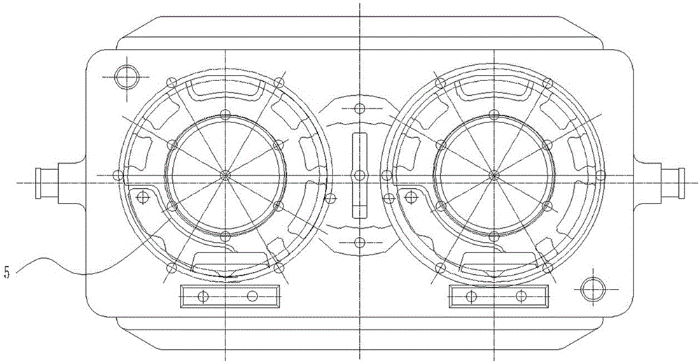
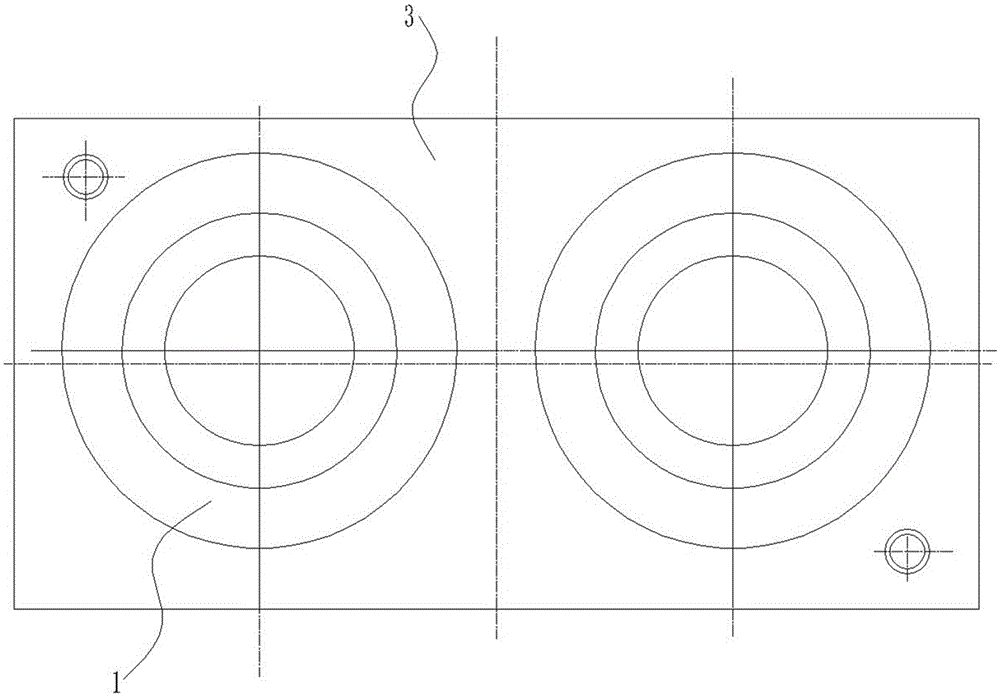
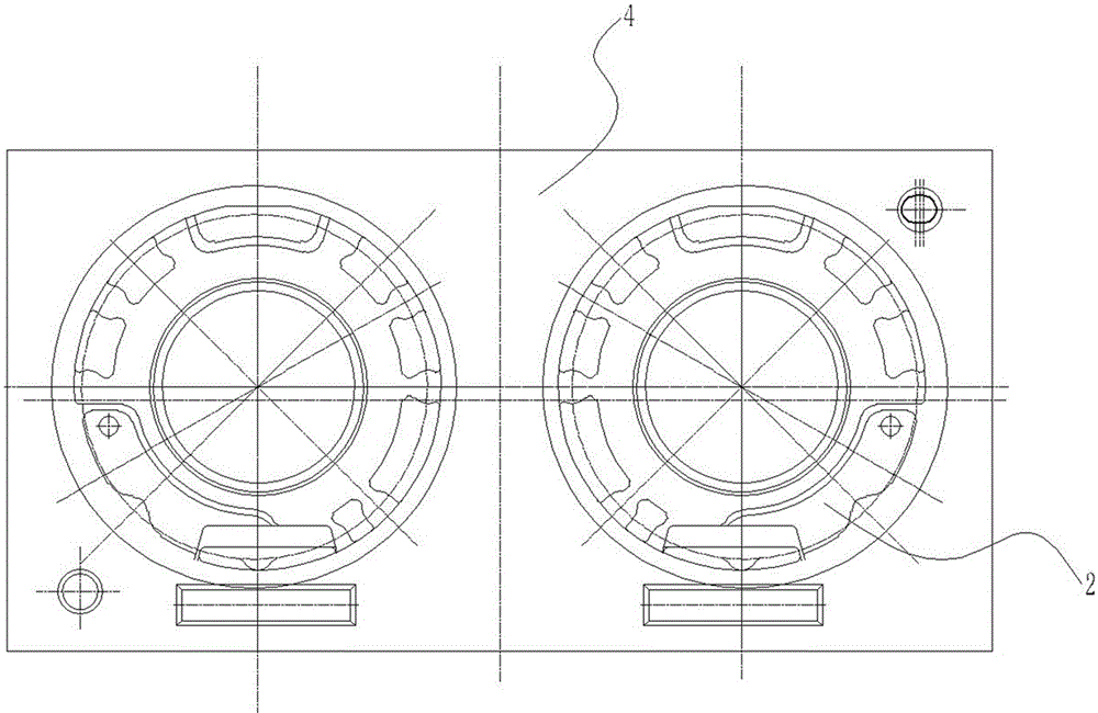
[0039] (1) Design and manufacture a set of upper and lower models that are completely consistent with the shape of the upper bearing cap of the subway locomotive as a master mold. The master mold includes the designed and manufactured bearing cap tooling mold, core box, pouring system, heating plate and base. Such as figure 2 , image 3 , Figure 6-9 As shown, the upper mold 1 is fixed on the upper mold plate 3, and the lower mold 2 is fixed on the lower mold plate 4. Two upper molds 1 are arranged side by side on the upper mold plate 3, and two upper molds 1 are arranged side by side on the lower mold plate 4. Two lower models 2, which can improve the efficiency of machining castings. The upper mold plate 3 and the lower mold plate 4 are respectively provided with exhaust valves for exhausting, so as to facilitate the di...

Embodiment 2

[0042] A method for casting an upper bearing cap of a subway locomotive by adopting an iron mold sand-covering process, comprising the following steps:

[0043] (1) Design and manufacture a set of upper and lower models that are completely consistent with the shape of the upper bearing cap of the subway locomotive as a master mold. The master mold includes the designed and manufactured bearing cap tooling mold, core box, pouring system, heating plate and base. Such as figure 2 , image 3 , Figure 6-9 As shown, the upper mold 1 is fixed on the upper mold plate 3, and the lower mold 2 is fixed on the lower mold plate 4. Two upper molds 1 are arranged side by side on the upper mold plate 3, and two upper molds 1 are arranged side by side on the lower mold plate 4. Two lower models 2, which can improve the efficiency of machining castings. The upper mold plate 3 and the lower mold plate 4 are respectively provided with exhaust valves for exhausting, so as to facilitate the di...

Embodiment 3

[0046] A method for casting an upper bearing cap of a subway locomotive by adopting an iron mold sand-covering process, comprising the following steps:

[0047] (1) Design and manufacture a set of upper and lower models that are completely consistent with the shape of the upper bearing cap of the subway locomotive as a master mold. The master mold includes the designed and manufactured bearing cap tooling mold, core box, pouring system, heating plate and base. Such as figure 2 , image 3 , Figure 6-9 As shown, the upper mold 1 is fixed on the upper mold plate 3, and the lower mold 2 is fixed on the lower mold plate 4. Two upper molds 1 are arranged side by side on the upper mold plate 3, and two upper molds 1 are arranged side by side on the lower mold plate 4. Two lower models 2, which can improve the efficiency of machining castings. The upper mold plate 3 and the lower mold plate 4 are respectively provided with exhaust valves for exhausting, so as to facilitate the di...


PUM

PropertyMeasurementUnit
tensile strengthaaaaaaaaaa
surface roughnessaaaaaaaaaa
tensile strengthaaaaaaaaaa

Abstract

The invention relates to a method for casting a bearing cap on a subway locomotive by using a sand faced permanent iron molding technology. According to the method, a complete cavity which is in the shape of the bearing cap is obtained through the sand faced permanent iron molding technology, a bearing cap part can be directly casted for a next core, so that the appearance and the inner quality of castings are improved effectively, scrappage of the castings is reduced, the weight of the castings is reduced by 20%, heat treatment and hole drilling processing are not required for the casted bearing cap, and shortcomings of inside shrinkage, a shrinkage cavity and cracks of the bearing cap are overcome effectively. In addition, the technology of the method is simple, a large amount of time, labor cost and equipment cost are saved, and the production efficiency of enterprises is improved greatly. By the method, production cost can be reduced by 35%, economic benefit is obvious, a market prospect is wide, and the method can be conveniently popularized and used for most of foundry enterprises.

Description

technical field [0001] The invention belongs to the field of casting, and in particular relates to a method for casting an upper bearing cover of a subway locomotive by adopting an iron mold sand-covering process. Background technique [0002] In existing industrial production, self-hardening sand molding technology is used to produce upper bearing cap castings of subway locomotives. The process has the following defects in the process of preparation: due to the slow cooling of molten iron in the no-hardening sand process, shrinkage porosity, shrinkage cavities, and cracks are generated inside the casting, and the quality is unstable; the cooling speed of the casting is slow, the internal structure is not compact, and the spheroidization level Low (level 3), the material is unstable, the appearance of the produced castings is rough and poor, the machining allowance of the castings is large, and the cast bearing cover castings are then processed by drilling, which not only wa...

Claims


Application Information

Patent Timeline
Patent Type & Authority Applications(China)
IPC IPC(8): B22C9/06B22C9/20
Inventor 温文林刘春晖冯奇宏杨永杰张永芳许沛沃
Owner 侯马市晋烽机械铸造有限公司
Learn More