Heat resisting device for copper part welding

A technology of heat resistance and copper parts, applied in the direction of auxiliary devices, welding equipment, auxiliary welding equipment, etc., to achieve the effect of ensuring welding quality

Inactive Publication Date: 2015-12-02
无锡市创新低温环模设备科技有限公司
View PDF8 Cites 6 Cited by
  • Summary
  • Abstract
  • Description
  • Claims
  • Application Information

AI Technical Summary

Problems solved by technology

[0003] The object of the present invention is to provide a heat-resistant device for welding copper parts to solve the above-mentioned problems in the prior art when welding copper in vacuum vessels

Method used


Image

  • Heat resisting device for copper part welding

Examples


Embodiment Construction

[0014] The technical solutions of the present invention will be further described below in conjunction with the accompanying drawings and through specific implementation methods.

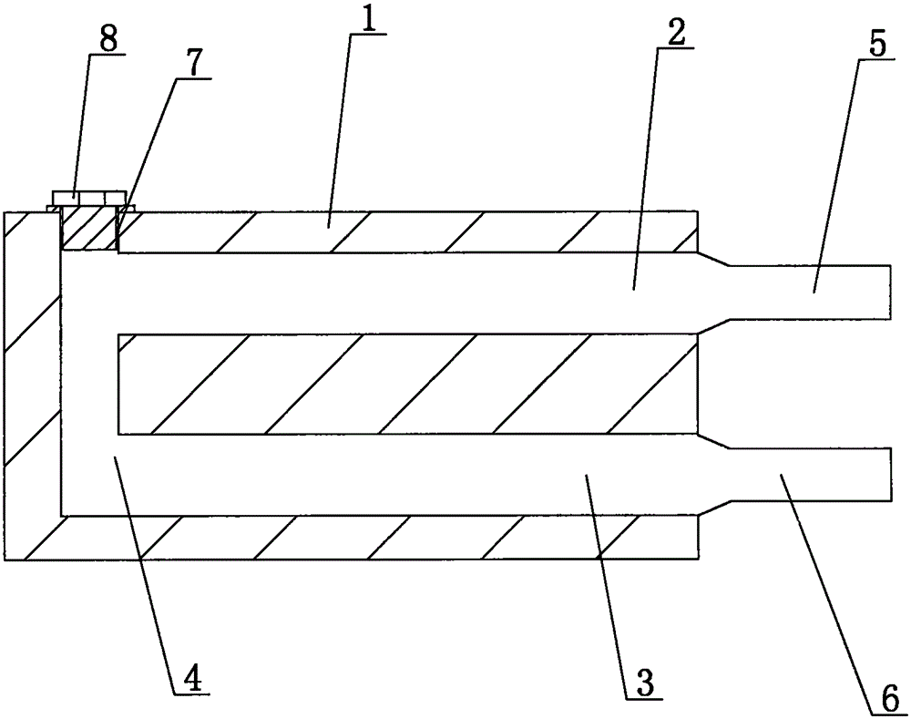
[0015] see figure 1 as shown, figure 1 It is a cross-sectional view of the splint of the heat resistance device for welding copper parts provided in Embodiment 1 of the present invention.

[0016] In this embodiment, a heat resistance device for welding copper parts includes two splints 1 with the same structure, and one end of the splint 1 is separated with a water inlet 2 and a water outlet 3, and the water inlet 2 and the water outlet 3 are communicated through the cooling water channel 4 opened in the splint 1, and the water inlet 2 and the water outlet 3 are welded with a water inlet 5 and a water outlet 6, so that they can be connected to the cooling water when they are ready for use. Yes, the cross-section of the cooling water channel 4 has a "匚"-shaped structure, and a channel processing h...


PUM


Abstract

The invention discloses a heat resisting device for copper part welding. The heat resisting device for copper part welding comprises two clamping plates which are made of metal and of the same structure. A water inlet and a water outlet are formed in one end of each clamping plate in a spaced mode. The water inlet and the water outlet in each clamping plate are communicated through a cooling water channel formed in the clamping plate. Water inlet pipes and water outlet pipes are welded outside the water inlets and the water outlets respectively. During welding, a welded copper part is clamped through the two clamping plates. When the heat resisting device is used during copper part welding, the welded copper part is clamped through the two clamping plates, circulating cooling water is introduced into the two clamping plates to be used for cooling the cooper part during welding, in this way, it can be guaranteed that the color of the welded copper part is not changed, a protective layer bound on copper part is in a good condition instead of being damaged, and the welding quality of the cooper part is guaranteed.

Description

technical field [0001] The invention belongs to the welding technology of copper parts, in particular to a heat resistance device for welding copper parts. Background technique [0002] Copper is often welded in the manufacture of vacuum containers. Some welded parts have been treated before welding or wrapped with a soft protective layer to prevent surface scratches. When welding, it is necessary to consider how to weld the workpiece and not It has an impact on the workpiece, because the heat conduction of copper is very fast when welding copper. If effective heat insulation measures are not taken, the protective layer wrapped on it will be destroyed after welding is completed. Contents of the invention [0003] The object of the present invention is to provide a heat resistance device for welding copper parts to solve the above-mentioned problems existing in the vacuum vessel welding copper in the prior art. [0004] For reaching this purpose, the present invention adop...

Claims


Application Information

Patent Timeline
Patent Type & Authority Applications(China)
IPC IPC(8): B23K37/00B23K37/04
CPCB23K37/003B23K37/0435
Inventor 张晓峰
Owner 无锡市创新低温环模设备科技有限公司
Why Eureka
Try Eureka