Valve body clamp for vertical machine tool

A fixture and machine tool technology, applied in the field of valve body fixtures for vertical machine tools, can solve problems such as waste of materials, difficult processing, and complex structures, and achieve the effects of improving product quality, ensuring clamping positions, and reducing costs

Active Publication Date: 2015-12-02
南通高中压阀门有限公司
View PDF13 Cites 4 Cited by
  • Summary
  • Abstract
  • Description
  • Claims
  • Application Information

AI Technical Summary

Problems solved by technology

[0002] At present, the sealing surface of the valve body of the wedge gate valve or the sealing surface of the swing check valve used in the vertical machine tool needs to be clamped by a general fixture before processing, but the fixtures currently used generally have The valve bodies of wedge gate valves or swing check valves of various sizes and specifications have poor versatility, and it is difficult to ensure that the sealing surfaces of the two opposite valve bodies are positioned accurately and symmetrically. At the same time, the current fixture The structure is relatively complex. Due to the large volume of the fixture itself, the complex structure brings difficulties in processing and wastes a lot of materials

Method used


Image

  • Valve body clamp for vertical machine tool
  • Valve body clamp for vertical machine tool
  • Valve body clamp for vertical machine tool

Examples


Embodiment Construction

[0016] The present invention will be further described in detail below in conjunction with the accompanying drawings and examples. The following examples are explanations of the present invention and the present invention is not limited to the following examples.

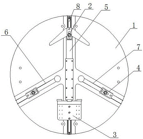
[0017] As shown in the figure, a valve body clamp for a vertical machine tool of the present invention includes a clamp body 1 , a V-shaped clamp 2 , an orientation clamp 3 and two side clamps 4 . The clamp body 1 is provided with a first T-shaped channel 5, a second T-shaped channel 6 and a third T-shaped channel 7, and the second T-shaped channel 6 and the third T-shaped channel 7 are arranged in the first T-shaped The channels 5 are symmetrically arranged on both sides of the first T-shaped channel 5, the first T-shaped channel 5 is provided with a reverse thread screw 8, and the V-shaped clamp 2 is slidably arranged on the first T-shaped channel 5 At one end, the orientation fixture 3 is slidably arranged at the...


PUM


Abstract

The invention discloses a valve body clamp for a vertical machine tool. The valve body clamp comprises a clamp body, a V-shaped clamp, a directional clamp and two side clamps. The clamp body is provided with a first T-shaped channel, a second T-shaped channel and a third T-shaped channel. The second T-shaped channel and the third T-shaped channel are symmetrically arranged at the two sides of the first T-shaped channel with the first T-shaped channel serving as the axis of symmetry. A reverse thread lead screw is arranged in the first T-shaped channel, the V-shaped clamp is arranged at one end of the first T-shaped channel in a sliding mode, the directional clamp is arranged at the other end of the first T-shaped channel in a sliding mode, and the two side clamps are arranged in the second T-shaped channel and the third T-shaped channel in a sliding mode respectively. The valve body clamp is simple in structure and low in cost, a valve is accurately positioned, and the product quality is improved.

Description

technical field [0001] The invention relates to a valve body clamp, in particular to a valve body clamp for a vertical machine tool. Background technique [0002] At present, the sealing surface of the valve body of the wedge gate valve or the sealing surface of the swing check valve used in the vertical machine tool needs to be clamped by a general fixture before processing, but the fixtures currently used generally have The valve bodies of wedge gate valves or swing check valves of various sizes and specifications have poor versatility, and it is difficult to ensure that the sealing surfaces of the two opposite valve bodies are positioned accurately and symmetrically. At the same time, the current fixture The structure is relatively complicated, and because the fixture itself is large in size, the complex structure brings difficulties in processing and wastes a lot of materials. Contents of the invention [0003] The technical problem to be solved by the present inventi...

Claims


Application Information

Patent Timeline
IPC IPC(8): B23Q3/06
CPCB23Q3/062
Inventor 陈崇南
Owner 南通高中压阀门有限公司
Why Eureka
Try Eureka