Pneumatic clamping mechanism

A clamping mechanism and pneumatic technology, applied in workpiece clamping devices, manufacturing tools, etc., can solve the problems of complicated production and complex overall structure, and achieve the effect of large clamping range, simple overall structure and simple mechanical movement.

Inactive Publication Date: 2015-12-02
NANTONG HUAXING OIL EQUIP
View PDF0 Cites 23 Cited by
  • Summary
  • Abstract
  • Description
  • Claims
  • Application Information

AI Technical Summary

Problems solved by technology

The traditional pneumatic clamping mechanism uses a pneumatic chuck to clamp the clamping block by compressing the internal air. The overall structure is complex and the production is complicated. Therefore, it is necessary to develop a pneumatic clamping mechanism with a simple structure and simple production. After searching, no technical solutions identical or similar to the present invention were found

Method used


Image

  • Pneumatic clamping mechanism
  • Pneumatic clamping mechanism

Examples


Embodiment Construction

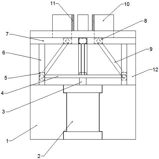
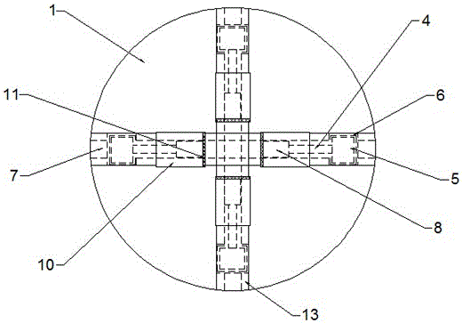
[0017] Such as figure 1 with figure 2 As shown, the present invention discloses a pneumatic clamping mechanism, which includes a chuck body 1, a cylinder 2 arranged inside the chuck body 1, a clamping mechanism and a guiding mechanism.

[0018] The chuck body 1 is in the shape of a circular column, with a cavity 12 for the guide mechanism on one side, a through hole for the cylinder 2 in the middle of the other side, and four chutes for the clamping mechanism at the end 13, the chute 13 communicates with the cavity 12.

[0019] The cylinder 2 is arranged in the through hole of the chuck body 1, the piston rod 3 points to one side of the cavity 12, two push rods 4 are connected to the piston rod 3, and a slider group A5 is respectively arranged at both ends of the push rod 4.

[0020] The clamping mechanism includes clamping blocks 10 nestedly fitted in the chute 13 , each clamping end of the clamping blocks 10 is provided with a rubber anti-skid pad 11 , and the bottom end ...


PUM


Abstract

The invention relates to a pneumatic clamping mechanism which comprises a chuck body, an air cylinder, a plurality of clamping mechanisms and a guiding mechanism, wherein a cavity for placing the guiding mechanism is formed at one side inside the chuck body; sliding chutes for placing the plurality of clamping mechanisms are formed in the end part of the chuck body; a push rod is connected onto a piston rod of the air cylinder; one sliding block group A is arranged at each of two ends of the push rod; each clamping mechanism comprises a clamping block arranged in the corresponding sliding chute; a sliding block group B is connected to the bottom end of each clamping block; the guiding mechanism comprises guide rails A, guide rails B and a crank; the guide rails A are arranged in the cavity; the sliding block groups A are in inserted fit with the insides of the guide rails A; two ends of the crank are respectively hinged to the sliding block group A and the sliding block group B which are positioned at the lower end of the same sliding chute. The pneumatic clamping mechanism disclosed by the invention has the advantages of consisting of the air cylinder and a crank sliding block mechanism, being simple in mechanical motion and integral structure, and being easy to process; a clamping block is clamped by the motion of pushing the crank sliding block mechanism through the air cylinder; higher precision can be obtained; meanwhile, the pneumatic clamping mechanism is quick in clamping process, so that the working efficiency is improved.

Description

technical field [0001] The invention relates to a clamping mechanism, in particular to a pneumatic clamping mechanism. Background technique [0002] The pneumatic clamping mechanism mainly utilizes the drive of the cylinder to clamp the material, thus facilitating processing. The traditional pneumatic clamping mechanism uses a pneumatic chuck to clamp the clamping block by compressing the internal air. The overall structure is complex and the production is complicated. Therefore, it is necessary to develop a pneumatic clamping mechanism with simple structure and simple production. After searching, no technical solutions identical or similar to the present invention are found. Contents of the invention [0003] The technical problem to be solved by the present invention is to provide a pneumatic clamping mechanism with simple structure and simple manufacture. [0004] In order to solve the above-mentioned technical problems, the technical solution of the present invention...

Claims


Application Information

Patent Timeline
Patent Type & Authority Applications(China)
IPC IPC(8): B25B11/00
CPCB25B11/00
Inventor 唐生荣林航
Owner NANTONG HUAXING OIL EQUIP
Why Eureka
Try Eureka