A method for increasing nitrogen by blowing nitrogen at the bottom of a ladle

A bottom blowing nitrogen and ladle technology, applied in the field of alloy smelting, can solve the problems of difficult selection of nitrogen and argon switching points, low end point hit rate, complicated operation, etc., to avoid low nitrogen increase control accuracy, avoid high costs, and save the effect of using

Active Publication Date: 2017-04-26
SHIJIAZHUANG IRON & STEEL
View PDF3 Cites 0 Cited by
  • Summary
  • Abstract
  • Description
  • Claims
  • Application Information

AI Technical Summary

Problems solved by technology

Ladle top blowing nitrogen requires an additional top blowing spray gun. During use, it is rarely used due to high molten steel temperature, low spray gun life, unstable nitrogen yield, and difficult nitrogen content to hit the target.
Although the addition of nitride alloys can ensure a high yield of nitrogen, the production cost is relatively high
For example, the Chinese Patent Publication No. CN103146875A discloses a method for smelting high-nitrogen steel under normal pressure. It needs to add 25-35 kg of manganese nitride to smelt 1 ton of steel, and the alloy cost per ton of steel is as high as 175-145 yuan / t of steel.
The cost of nitrogen-increasing treatment by blowing nitrogen at the bottom of the ladle is lower than that of nitrided alloys, but the nitrogen yield of conventional bottom-blowing nitrogen-increasing methods is low and unstable, and it is difficult to hit the steel nitrogen mass fraction control target
For example, a kind of nitrogen alloying process disclosed by the Chinese patent of the publication number CN101538636A is carried out with nitrogen in a ladle furnace, and a kind of nitrogen-increasing method of nitrogen-containing pure steel disclosed by the Chinese patent of the publication number CN101168817A, all adopt pure nitrogen gas alloying first Nitrogen is alloyed by stirring with pure argon and removing excess nitrogen, but it is difficult to select the switching point of nitrogen and argon in this method, which is not only complicated to operate but also has a low hit rate at the end point

Method used


Image

  • A method for increasing nitrogen by blowing nitrogen at the bottom of a ladle
  • A method for increasing nitrogen by blowing nitrogen at the bottom of a ladle
  • A method for increasing nitrogen by blowing nitrogen at the bottom of a ladle

Examples


Embodiment 1

[0054] Embodiment 1: The method of blowing nitrogen at the bottom of the ladle to increase nitrogen adopts the following specific process.

[0055] The composition of nitrogen-containing steel is shown in Table 1, and the balance is Fe and unavoidable impurities.

[0056] Table 1: Composition (wt%) of nitrogen-containing steel

[0057] element C Si mn S Cr Al Ni content 0.19 0.09 1.32 0.023 1.20 0.027 0.007

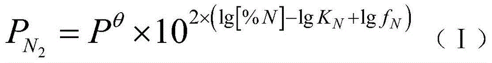
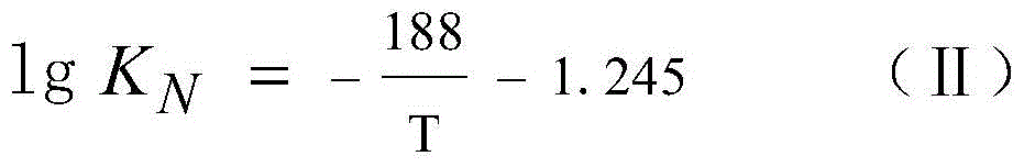
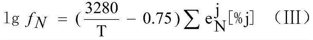
[0058] Calculate according to the above formulas (I), (II), (III) and the ingredients in Table 1. The calculation process is shown in formulas (1-1), (1-2), (1-3):

[0059]

[0060] The depth of molten steel is 2.8m, P 压损 Generally 0.4MPa, then:

[0061] P 总 =1.2(ρ 钢 gh+P 压损 )=0.73MPa (1-2)

[0062] P Ar =P 总 -P N2 =0.7181MPa (1-3)

[0063] Adjust the pressure of nitrogen and argon to the above calculated values ​​as required, and set the flow rate to 200Nl / min for bottom blowing nitrogen alloying; the quality of nitrogen i...

Embodiment 2

[0064] Embodiment 2: The method of blowing nitrogen at the bottom of the ladle to increase nitrogen adopts the following specific process.

[0065]The composition of nitrogen-containing steel is shown in Table 2, and the balance is Fe and unavoidable impurities.

[0066] Table 2: Composition (wt%) of nitrogen-containing steel

[0067] element C Si mn S Cr Al Ni Mo content 0.20 0.22 0.8 0.02 0.55 0.03 0.47 0.17

[0068] Calculate according to the above formulas (I), (II), (III) and the ingredients in Table 2. The calculation process is shown in formulas (2-1), (2-2), (2-3):

[0069]

[0070] The depth of molten steel is 2.9m, P 压损 Generally 0.4MPa, then:

[0071] P 总 =1.2(ρ 钢 gh+P 压损 )=0.74MPa (2-2)

[0072] P Ar =P 总 -P N2 =0.7164MPa (2-3)

[0073] Adjust the pressure of nitrogen and argon to the above calculated values ​​as required, and set the flow rate to 200Nl / min for bottom blowing nitrogen alloying; the quality of nitr...

Embodiment 3

[0074] Embodiment 3: The method of blowing nitrogen at the bottom of the ladle to increase nitrogen adopts the following specific process.

[0075] The composition of nitrogen-containing steel is shown in Table 3, and the balance is Fe and unavoidable impurities.

[0076] Table 3: Composition (wt%) of nitrogen-containing steel

[0077] element C Si mn S Cr Al Ni Mo content 0.17 0.25 0.58 0.015 1.65 0.030 1.50 0.28

[0078] Calculate according to the above formulas (I), (II), (III) and the ingredients in Table 3. The calculation process is shown in formulas (3-1), (3-2), (3-3):

[0079]

[0080] The depth of molten steel is 2.8m, P 压损 Generally 0.4MPa, then:

[0081] P 总 =1.2(ρ 钢 gh+P 压损 )=0.73MPa (3-2)

[0082] P Ar =P 总 -P N2 =0.6917MPa (3-3)

[0083] Adjust the nitrogen and argon pressures to the above calculated values ​​as required, and set the flow rate to 200Nl / min for bottom-blowing nitrogen alloying; the quality of ni...


PUM


Abstract

The inventiondiscloses a steel ladle bottom nitrogen blowing and adding method. The method process comprises the steps of firstly, calculating nitrogen partial pressure PN2 according to the formula (I); secondly, calculating the bottom blowing gas total pressure P<total> according to the formula (II); thirdly, calculating the argon partial pressure PAr according to the formula (III); and fourthly, setting pressure of the nitrogen and pressure of the argon according to the nitrogen partial pressure PN2 and the argon partial pressure PAr and performing steel ladle bottom blowing at the same time. According to the method, through control over the partial pressure of the nitrogen in the argon and nitrogen mixed gas in the steel ladle bottom nitrogen blowing process, nitrogen adding for nitrogenous steel can be achieved accurately, use of high-cost nitralloy is reduced, and the defect of low control accuracy of sectional bottom nitrogen blowing and adding is prevented; adding of the high-cost nitralloy can be prevented, and high nitrogen mass fraction hit rate can be guaranteed; the steel ladle bottom nitrogen blowing and adding method has the characteristics of being low in cost, high in hit rate and easy to operate.

Description

technical field [0001] The invention relates to an alloy smelting method, in particular to a method for increasing nitrogen by blowing nitrogen at the bottom of a ladle. Background technique [0002] With the progress of society and the development of technology, users have higher and higher requirements for the strength, toughness and processing performance of steel. Some high-strength steels use nitrided alloys to strengthen the performance of steel. The finished steel has certain requirements for nitrogen content, making The control of nitrogen content in steel has become a key technology for the smelting of these steels. In the process of steelmaking, nitrogen addition to molten steel can be carried out by blowing nitrogen from the top of the ladle, blowing nitrogen from the bottom, or adding nitrided alloys. Ladle top blowing nitrogen requires an additional top blowing spray gun, which is rarely used due to high molten steel temperature, low spray gun life, unstable ni...

Claims


Application Information

Patent Timeline
Patent Type & Authority Patents(China)
IPC IPC(8): C21C7/072
Inventor 董大西杨锋功胡云生张永战东平邱国兴姜周华
Owner SHIJIAZHUANG IRON & STEEL
Why Eureka
Try Eureka