Prefabricated reinforced concrete component and assembly type building comprising same

A reinforced concrete and component technology, which is applied to buildings, building components, building structures, etc., can solve the problems of inability to guarantee connection strength, inconvenient reinforcement construction, and unfavorable labor efficiency, so as to improve labor efficiency, simplify construction, and connect reliably. Effect

Active Publication Date: 2015-12-02
BEIJING EVEREST GREEN BUILDING TECH
View PDF9 Cites 17 Cited by
  • Summary
  • Abstract
  • Description
  • Claims
  • Application Information

AI Technical Summary

Problems solved by technology

However, when the above-mentioned components are connected, after the steel nails are penetrated, additional overlapping steel bars are required to convert the force in the thickness direction of the components into the connection force in the width direction of adjacent components. T

Method used


Image

  • Prefabricated reinforced concrete component and assembly type building comprising same
  • Prefabricated reinforced concrete component and assembly type building comprising same
  • Prefabricated reinforced concrete component and assembly type building comprising same

Examples


Embodiment 1

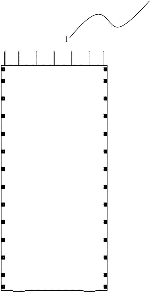
[0037] Such as figure 1 As shown, the prefabricated reinforced concrete member 1 of the present invention is prefabricated with concrete. Such as Figure 5As shown, the component 1 is provided with a through hole 11 running through its length direction. Both side plates of the component 1 are provided with grooves 12 parallel to the through holes 11 . This embodiment only takes the through hole 11 as a round hole and the cross section of the groove 12 as an example for illustration. The shape of the above-mentioned through hole 11 can also be set as an oval hole, a square hole or a semicircle at both ends according to actual operation requirements. There is a rectangular hole in the middle, and the cross section of the groove 12 can also be in the shape of a semi-ellipse, a rectangle, or a combination of a semi-circle and a rectangle.

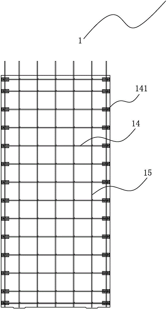
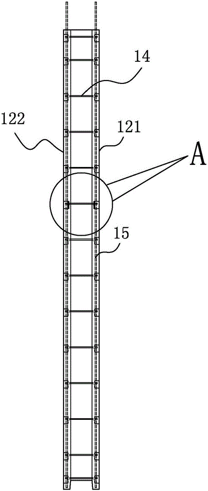
[0038] Such as Figure 2 to Figure 6 As shown, the component 1 includes an outer wall panel 121 adjacent to the above-mentioned side panel...

Embodiment 2

[0047] Such as Figure 12 As shown, the difference between this embodiment and the first embodiment is that the component 1' is only provided with a groove 12' on one side plate.

Embodiment 3

[0049] Such as Figure 13 As shown, the difference between this embodiment and Embodiment 1 is that the component 1 "is only provided with an embedded part 141 " at the left end of the transverse steel bar 14 ", and when in use, the operation on the right side with the embedded part 141 "is the same as The same as the first embodiment, the left end of the transverse steel bar 14 ″ without the embedded part 141 ″ is inserted into the floor concrete, which greatly increases the strength of the transverse connection between the member 1 ″ and the floor slab.


PUM


Abstract

The invention provides a prefabricated reinforced concrete component. A through hole which penetrates in the components in the length direction is formed in the component; a groove is formed in a side plate of the component; when two components are in butt joint with each other, the two grooves are in butt joint with each other to form a long hole; a plurality of longitudinal reinforcing steel bars which extend along the length direction of an external wall plate of the component is arranged in the external wall plate of the component along the width direction; a plurality of longitudinal reinforcing steel bars which extend along the length direction of an internal wall plate of the component is arranged in the internal wall plate of the component along the width direction; a plurality of transverse reinforcing steel bars which extend along the width direction of the external wall plate is arranged in the external wall plate along the length direction; a plurality of transverse reinforcing steel bars which extend along the width direction of the internal wall plate is arranged in the internal wall plate along the length direction; the transverse reinforcing steel bars and the longitudinal reinforcing steel bars are intersected to form a reinforcing mesh; an embedded piece is fixedly arranged at one end of each transverse reinforcing steel bar; and when the two components are spliced with each other, two side plates with grooves are spliced together through a connecting piece B. The prefabricated reinforced concrete component is simple in structure, convenient to connect and easy to operate; extra lap joint reinforcing steel bars are not required; construction is facilitated greatly; working efficiency is improved; and moreover, stress conversion does not exist during component connection, and the connection strength of the component is greatly improved.

Description

technical field [0001] The present invention relates to a relatively thin component used for building house components, in particular to a prefabricated reinforced concrete component made of concrete and an assembled building formed therefrom. Background technique [0002] China's construction field is undergoing technological innovation to realize technological upgrading and transformation in order to achieve the goal of modernization of construction. At present, the industry mainly adopts the industrial production of building component products in the factory and the assembly construction on the construction site to realize the industrial construction of housing, and use this to replace the traditional method of a large number of manual operations on site. Housing industrialization construction saves resources, saves manpower, reduces pollution, and protects the environment. It truly realizes green building construction, realizes housing industrialization construction, mee...

Claims


Application Information

Patent Timeline
IPC IPC(8): E04C2/30E04B2/64E04B1/61
Inventor 张英保廖丽英张裕照
Owner BEIJING EVEREST GREEN BUILDING TECH
Why Eureka
Try Eureka