a wind power plant
A technology for wind power generation devices and generators, which is applied to wind power generation, wind turbines, wind turbine combinations, etc., can solve the problems of low installation and maintenance flexibility and convenience, difficulty in improving wind energy utilization, transmission efficiency, and inability to eliminate many gearboxes. problems, etc., to facilitate installation and maintenance, reduce radius, and improve power generation efficiency
- Summary
- Abstract
- Description
- Claims
- Application Information
AI Technical Summary
Problems solved by technology
Method used
Image
Examples
Embodiment 1
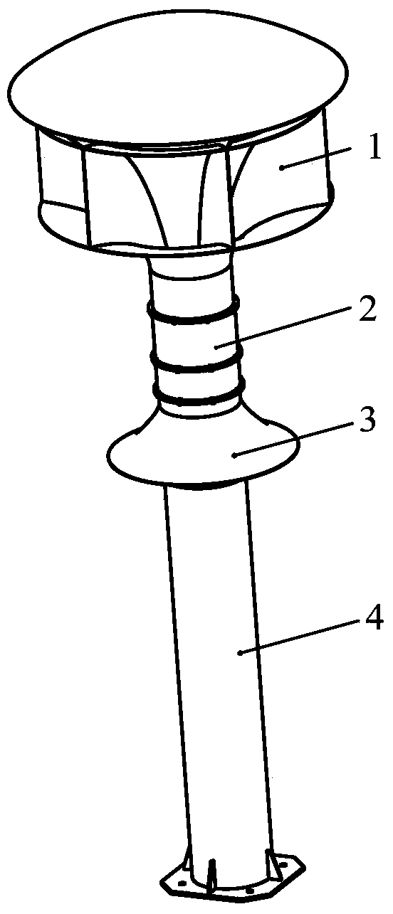
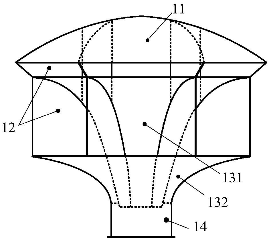
[0036] refer to figure 1 and figure 2 , figure 1 It is a schematic diagram of the overall mechanism of the wind power generation device provided by the embodiment of the present invention, figure 2 The structural schematic diagram of the air collector module provided for the embodiment of the present invention is described in detail as follows:
[0037] The wind power generation device consists of 4 modules, including wind collector module 1, generator module 2, exhaust module 3 and support module 4;
[0038] The air collector module is provided with an air guide pipe, and an air collection port 14 communicating with the air guide pipe;
[0039] The power generation module is provided with a pipe connected to the air collecting port 14, and a generator assembly in which the blades are connected with the inner rotor in the pipe.
[0040] Wherein, there is a mounting structure on the inner wall or the outer wall of the air collector module, and the power generation module ...
Embodiment 2
[0047] refer to figure 1 and figure 2 , the present embodiment mainly describes the use of each component in the air collector module 1, detailed as follows:
[0048]The top of the wind collector module 1 is a thin-walled end cover 11, which is used to prevent rainwater. The end cover 11 is connected to the inner air guide pipe 131 through the rib plate 12 . The inner air guide pipe 131 and the outer layer air guide pipe 132 are also connected by ribs 12 . Due to the existence of the ribs 12 , the air introduced from each air inlet has little influence on other air inlets, and will not flow out from other air inlets, so that the introduced air flows to the air collecting port 14 .
[0049] In the embodiment of the present invention, the air introduced through the air inlet will drive the air at the lower port of the inner air guide pipe to flow downward, thereby reducing the wind pressure here and forming a pressure at the upper and lower ports of the inner air guide pipe....
Embodiment 3
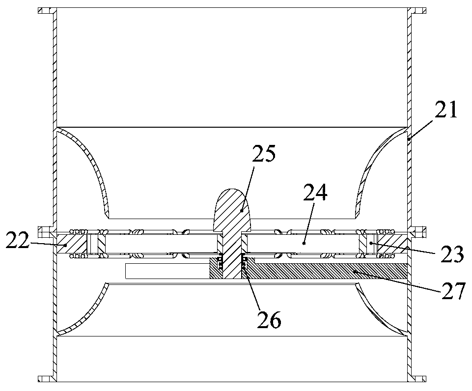
[0051] refer to image 3 and Figure 4 , image 3 It is a schematic diagram of the full section of the generator module provided by the embodiment of the present invention, Figure 4 The exploded schematic diagram of the generator module provided by the embodiment of the present invention is described in detail as follows:
[0052] The outer wall of the generator module 2 is connected by the upper thin-walled cylinder 211 and the lower thin-walled cylinder 212 through flanges, the support frame 27 is fixed on the inner wall of the lower layer thin-walled cylinder 212, and the inner rotor 24 of the motor is installed above the support frame 27 through the shaft 25 and the bearing group 26 . The inner and outer rings of the inner rotor 24 of the motor are connected by thin-walled blades, and one end of the shaft 25 is made into a fairing form to adjust the wind direction so that more air passes through the blades connected to the inner rotor. The magnetic poles 23 are surfac...
PUM
 Abstract
Description
Claims
Application Information
 - R&D
- Intellectual Property
- Life Sciences
- Materials
- Tech Scout
- Unparalleled Data Quality
- Higher Quality Content
- 60% Fewer Hallucinations
Browse by: Latest US Patents, China's latest patents, Technical Efficacy Thesaurus, Application Domain, Technology Topic, Popular Technical Reports.
© 2025 PatSnap. All rights reserved.Legal|Privacy policy|Modern Slavery Act Transparency Statement|Sitemap|About US| Contact US: help@patsnap.com


