Low-power-consumption and large-flow high-speed switching valve

A high-speed switching valve and high-flow technology, which is applied in the direction of fluid pressure actuators, servo motor components, mechanical equipment, etc., can solve the problems of limiting the application range of hydraulic high-speed punching machines and cannot be applied, and achieve low cost, easy processing, and valves. The effect of small flow pressure loss at the port

Active Publication Date: 2015-12-02
OCEAN RES CENT OF ZHOUSHAN ZHEJIANG UNIV
View PDF6 Cites 2 Cited by
  • Summary
  • Abstract
  • Description
  • Claims
  • Application Information

AI Technical Summary

Problems solved by technology

Therefore, under the condition of high-frequency stamping, the existing hydraulic high-speed punching machines are only suitable for punching and punching of thin sheet metal, but cannot be applied to processing of thicker sheet metal and deep stamping with larger strokes, which seriously limits the hydraulic pressure. The scope of application of high-speed punch

Method used


Image

  • Low-power-consumption and large-flow high-speed switching valve
  • Low-power-consumption and large-flow high-speed switching valve

Examples


Embodiment Construction

[0015] The present invention will be further described below in conjunction with the accompanying drawings and embodiments.

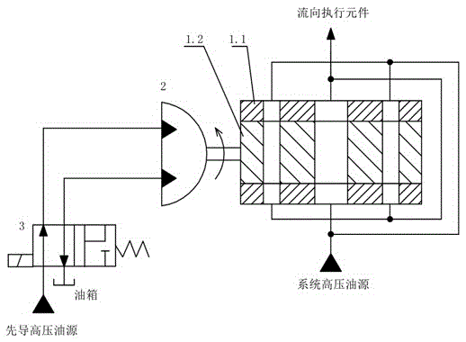
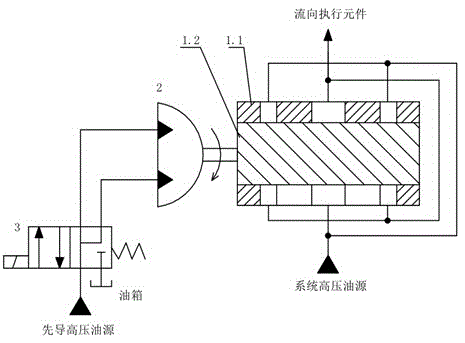
[0016] Such as figure 1 As shown, the present invention is made up of valve sleeve 1.1, spool 1.2, differential swing cylinder 2 and high-speed switching valve 3. The spool 1.2 is installed in the valve sleeve 1.1, forming a rotary valve type main valve structure. The spool 1.2 has three straight flow passages in the radial direction, and the three flow passages are distributed in sequence along the axial direction, and the centerlines of two adjacent flow passages have an equal distance in the axial direction; the two end flow passages The flow areas are equal, and the sum of the two flow areas is equal to the flow area of ​​the middle channel. The valve sleeve 1.1 has a straight-through flow channel at the position corresponding to the flow channel of the valve core 1.2, which has the same shape as the flow channel of the valve core 1.2. The direct...


PUM


Abstract

The invention discloses a low-power-consumption and large-flow high-speed switching valve. The switching valve is of a rotary valve structure. Rotation of a valve element of the switching valve is controlled by a differential swinging cylinder. The rotating direction of the differential swinging cylinder is controlled through a two-position four-way high-speed switching valve body. Three through flow passages are formed in the valve element in the radial direction and sequentially distributed in the axial direction, and the distances between the center lines of the adjacent flow passages in the axial direction are equal. The passage area of the middle flow passage is twice the passage areas of the two end flow passages, and the passage areas of the two end flow passages are equal. The flowing direction of oil in the middle flow passage is opposite to the flowing direction of oil in the two end flow passages. Inlets and outlets of the three flow passages are communicated respectively. When the high-speed switching valve body is in the totally-opening state, the flow passages are in a through pipe type, the passage pressure losses of a valve opening are small, and low-power-consumption and large-flow flowing of oil can be achieved.

Description

technical field [0001] The invention relates to a high-speed on-off valve with low power consumption and large flow, in particular to a high-speed on-off valve suitable for hydraulic high-speed presses. Background technique [0002] Hydraulic high-speed punching machine is an advanced basic processing equipment in modern manufacturing industry. It relies on hydraulic main control valve to control hydraulic cylinder to realize high-speed punching action. The hydraulic main control valve directly determines the punching force, punching stroke and punching frequency of the hydraulic press. [0003] At present, hydraulic high-speed punching machines usually use servo valves as hydraulic main control valves. However, due to the large pressure loss at the valve port of the servo valve, the working performance of the hydraulic high-speed punching machine is limited. The punching force of the existing hydraulic high-speed punching machine under the high-frequency punching conditio...

Claims


Application Information

Patent Timeline
Patent Type & Authority Applications(China)
IPC IPC(8): F15B13/02
Inventor 丁凡宋伟刘硕方辉蔡勇沈莹杰
Owner OCEAN RES CENT OF ZHOUSHAN ZHEJIANG UNIV
Why Eureka
Try Eureka