Axial-radial electrically-excited magnetic bearing

An axial radial and electric excitation technology, applied in the field of axial radial electric excitation magnetic bearings, can solve the problems of large volume, weight and power consumption, and high rigidity of magnetic suspension bearings, and achieve fewer power circuits and small control variables , low cost effect

Active Publication Date: 2015-12-02
NANJING UNIV OF POSTS & TELECOMM
View PDF10 Cites 12 Cited by
  • Summary
  • Abstract
  • Description
  • Claims
  • Application Information

AI Technical Summary

Problems solved by technology

The active magnetic suspension bearing establishes a bias magnetic field in the air gap through the bias winding with direct current, and establishes a control magnetic field in the air gap through the control winding with alternating current whose size and direction are controlled in real time. The superposition and cancellation of the magnetic field in the air gap produces a magnetic field attraction whose size and direction can be actively controlled, thereby realizing the stable suspension of the rotor. This type of magnetic suspension bearing has high rigidity and can be precisely controlled, but the unit bearing capacity required The size, weight and power consumption are relatively large

Method used


Image

  • Axial-radial electrically-excited magnetic bearing
  • Axial-radial electrically-excited magnetic bearing
  • Axial-radial electrically-excited magnetic bearing

Examples


Embodiment Construction

[0032] The technical scheme of an axial radial electric excitation magnetic bearing of the present invention will be described in detail below in conjunction with the accompanying drawings:

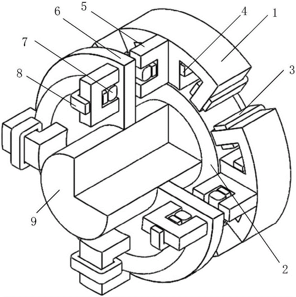
[0033] like figure 1 As shown, it is a three-dimensional structural schematic diagram of an axial radial electric excitation magnetic bearing embodiment 1 of the present invention, wherein, 1 is a radial magnetic bearing stator, 2 is a radial suspension rotor, 3 is a radial suspension winding, and 4 is Bias winding, 5 is an axial magnetic bearing stator, 6 is an axial suspension rotor, 7 is an axial suspension winding, 8 is an axial bias winding, and 9 is a rotating shaft.

[0034] An axial radial electric excitation magnetic bearing, comprising a radial magnetic bearing stator, an axial magnetic bearing stator, a radial suspension rotor, an axial suspension rotor, a bias winding, a radial suspension winding, and an axial suspension winding;

[0035] The radial magnetic bearing stator is...


PUM


Abstract

The invention discloses an axial-radial electrically-excited magnetic bearing. Stators of the magnetic bearing comprise E-shaped stators and C-shaped stators, wherein rotors comprise radial suspension rotors and axial suspension rotors; windings comprise a bias winding, an radial suspension winding and an axial suspension winding; the radial suspension winding comprises two suspension windings in radial direction; both the number of the E-shaped stators and the number of the C-shaped stators are 4; the middle tooth width of each E-shaped stator is two times to that of other two teeth; the radial suspension rotors and the axial suspension rotors are cylindrical structures; the bias winding is capable of simultaneously providing radial bias magnetic flux and axial bias magnetic flux; the radial suspension winding is capable of controlling radial suspension; the axial suspension winding is capable of controlling axial suspension. Through the axial-radial electrically-excited magnetic bearing, the axial suspension force and the radial suspension force are decoupled with each other; two radial suspension forces are also decoupled with each other; magnetic circuits are isolated from one another; the magnetic bearing is high in fault-tolerance performance, few in control variables, simple to control and few in power circuits.

Description

technical field [0001] The invention relates to an axial radial electric excitation magnetic bearing, which belongs to the field of magnetic suspension bearings. Background technique [0002] Magnetic suspension bearings can be divided into three types: active type, passive type and hybrid type according to the way the magnetic field is established. The active magnetic suspension bearing establishes a bias magnetic field in the air gap through the bias winding of direct current, and establishes a control magnetic field in the air gap through the control winding of alternating current whose size and direction are controlled in real time. The superposition and cancellation of the magnetic field in the air gap produces a magnetic field attraction whose size and direction can be actively controlled, thus realizing the stable suspension of the rotor. This type of magnetic bearing has high rigidity and can be precisely controlled, but it needs to produce a unit bearing capacity. ...

Claims


Application Information

Patent Timeline
Patent Type & Authority Applications(China)
IPC IPC(8): F16C32/04
Inventor 刘泽远梅磊杨艳曹鑫邓智泉
Owner NANJING UNIV OF POSTS & TELECOMM
Why Eureka
Try Eureka