Fiber-optic gyroscope and inertial measurement unit automated multi-channel test system
A fiber optic gyroscope and testing system technology, applied in measurement devices, instruments, etc., can solve the problems of limited testing efficiency, low production efficiency, low efficiency, etc., and achieve the effect of easy monitoring and control
Active Publication Date: 2015-12-02
BEIJING AEROSPACE TIMES OPTICAL ELECTRONICS TECH
View PDF6 Cites 22 Cited by
- Summary
- Abstract
- Description
- Claims
- Application Information
AI Technical Summary
Problems solved by technology
Due to the large amount of equipment involved in the testing process, manual operation of the equipment is not only inefficient, but also prone to errors and affects product quality. If the automatic control of the testing process can be realized according to preset parameters, it will not only solve the problem of low production efficiency , can also improve the consistency and accuracy of the testing process, so that the product quality can be more effectively guaranteed
[0003] The existing automated measurement and control are all researched on a single item in the test system, and it is impossible to control the test system as a whole to achieve integrated multi-threaded automatic measurement and control, which leads to testers always implementing semi-automatic control of the test process, unable to Overall control of the entire process, this method is relatively limited in improving test efficiency, and more human participation is involved, making it difficult to achieve real automated control of the test system
Method used
View moreImage
Smart ImageViewing Examples

Examples
Embodiment
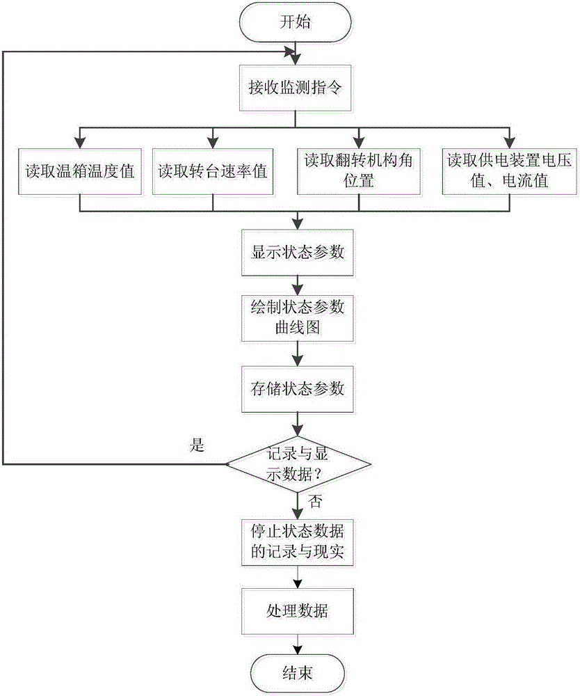
[0095] Adopt the fiber optic gyroscope of the present invention and inertial group automatic multi-channel testing system to carry out the method flow process of product testing as follows Figure 4 shown. In this embodiment, the high and low temperature rate test is taken as an example for illustration.
Login to View More PUM
 Abstract
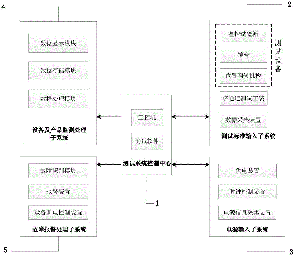
The invention discloses a fiber-optic gyroscope and inertial measurement unit automated multi-channel test system. The system comprises a control center 1, a test standard input subsystem 2, a power input subsystem 3, an equipment and product monitoring and processing subsystem 4 and a fault alarm processing subsystem 5. The fiber-optic gyroscope and inertial measurement unit automated multi-channel test system disclosed by the invention achieves multi-threading collaborative control on the test standard input subsystem and the power input subsystem by refining standard input equipment and product state parameters in a product test process, and developing a system test and control center embedded into automated test software by matching with a sequential control algorithm, so as to achieve the functions such as real-time parallel acquisition, display, sorting, storage and analysis of multi-channel data of equipment states and products, uses a sound and light alarm device for giving an alarm after the identification of a fault mode, and carries out power-off processing on equipment in failure synchronously, thus forming the fiber-optic gyroscope and inertial measurement unit automated multi-channel and fault self-processing test system, and effectively improving the consistency and reliability of the whole product test process.
Description
technical field [0001] The invention relates to the technical field of fiber optic gyroscope and inertial group testing, in particular to an automatic multi-channel testing system for fiber optic gyroscope and inertial group, which is used for simultaneous automatic testing of multiple sets of fiber optic gyroscopes and inertial groups. Background technique [0002] The fiber optic gyroscope and inertial group test system is a necessary tool for the fiber optic gyroscope and inertial group adjustment test. The test of fiber optic gyroscope and inertial group generally uses thermostat, turntable, flipping mechanism, power supply and other equipment to test the position, speed and temperature of inertial group. During the test, the test equipment needs to be controlled to meet the requirements of the test process. . Due to the large amount of equipment involved in the testing process, manual operation of the equipment is not only inefficient, but also prone to errors and affe...
Claims
Login to View More Application Information
Patent Timeline
 Patent Type & Authority Applications(China)
IPC IPC(8): G01C25/00
CPCG01C25/00G01C25/005
Inventor 陶钧刘浩王华张宇陈晓双李梅娟时东海吴义峰王效昆
Owner BEIJING AEROSPACE TIMES OPTICAL ELECTRONICS TECH