Measuring device of friction coefficient of papilionaceous optical cable and measuring method of measuring device

A friction coefficient and measuring equipment technology, applied in measuring devices, instruments, and mechanical devices, etc., can solve problems such as difficulty in ensuring uniform speed, prone to displacement, inaccurate traction force, etc., to reduce human and equipment errors and ensure accuracy. and reliability, reducing waste of raw materials

Inactive Publication Date: 2015-12-02
JIANGSU ZHONGTIAN TECH CO LTD
View PDF5 Cites 3 Cited by
  • Summary
  • Abstract
  • Description
  • Claims
  • Application Information

AI Technical Summary

Problems solved by technology

[0004] The above test method has been used by various domestic optical cable manufacturers for a long time to test the surface friction coefficient of the butterfly optical cable. Although the equipment method is simple and effective, it contains many problems that may cause inaccurate or even serious deviations in the measurement results.
The manual traction of the spring tension gauge in the horizontal direction is difficult to ensure a uniform speed, and the upper and lower metal plates are prone to displacement under the influence of the optical cable under test, and the manual traction is not easy to stabilize, and the human error has a great influence, resulting in inaccurate measured actual traction force

Method used


Image

  • Measuring device of friction coefficient of papilionaceous optical cable and measuring method of measuring device
  • Measuring device of friction coefficient of papilionaceous optical cable and measuring method of measuring device

Examples


Embodiment Construction

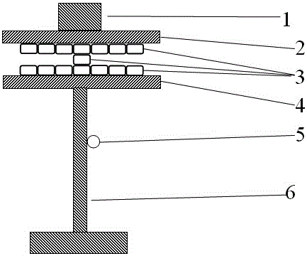
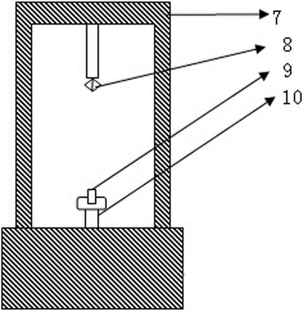
[0021] Such as figure 1 , 2 As shown, a measuring device for the friction coefficient of a butterfly optical cable includes a friction coefficient test bench, an electronic universal testing machine, a computer terminal and an electronic balance. The friction coefficient test bench includes a base with a height adjustment knob, and a stainless steel The cover plate and the bottom plate are placed parallel to each other up and down. There is a weight on the top of the cover plate. A tension arm and a pulley bracket are fixed on the electronic universal testing machine. The pulley bracket is located directly below the tension arm. A clamp is installed at the end of the tension arm. There are fixed pulleys.

[0022] A method for measuring a measuring device for a butterfly optical cable friction coefficient, comprising the steps of:

[0023] Step 1: Adjust the position of the fixture to the starting position of the electronic universal testing machine, select a fixed pulley wit...


PUM


Abstract

The invention discloses a measuring device of the friction coefficient of a papilionaceous optical cable. The measuring device comprises a friction coefficient test bed, an electronic universal testing machine, a computer terminal and an electronic scale. The friction coefficient test bed comprises a base with a height adjusting knob, a cover plate and a bottom plate which are horizontally parallel and are placed in the vertical direction are arranged above the base, a tension arm and a pulley support with a fixed pulley are arranged on the electronic universal testing machine, and a clamp is mounted at the tail end of the tension arm. A measuring method comprises the steps that small tested optical cable segments equal in length are cut out, and are densely arranged and pasted on strong double sticky tapes on the cover plate and the bottom plate, the bottom plate and the lower edge of the fixed pulley are made to be horizontal, a large tested optical cable segment is taken and fixed, and a switch of the electronic universal testing machine is turned on to start testing. According to the measuring device, manual operation can be simplified, testing efficiency can be improved, and friction coefficient data at the initial stage of production or experiments can be measured and found in time, so that raw material waste of subsequent production can be reduced; besides, human and equipment errors are reduced to the maximum extent, and the accuracy and reliability of the product testing result are effectively guaranteed.

Description

technical field [0001] The invention belongs to the field of communication optical cable manufacturing, and relates to a measuring device and a measuring method for the surface friction coefficient of a butterfly optical cable. The measuring device and the measuring method of the invention are suitable for measuring the surface friction coefficient of butterfly optical cables of various specifications. Background technique [0002] Butterfly optical cable is the most common lead-in optical cable in the construction of fiber-to-the-home projects. After years of development, low-friction butterfly optical cables have been derived in developed regions such as Europe and the United States, and have been put into use in large quantities. Friction characteristics, to achieve the purpose of effectively reducing the friction coefficient between the surfaces of multiple butterfly optical cables, so as to save construction time and improve construction efficiency in complex and crowded...

Claims


Application Information

Patent Timeline
IPC IPC(8): G01N19/02G02B6/44
CPCG01N19/02G02B6/44
Inventor 尤徐周华许军陈小建
Owner JIANGSU ZHONGTIAN TECH CO LTD
Why Eureka
Try Eureka