Capacitance detection circuit and capacitance sensing circuit
A capacitance detection and detection circuit technology, applied in the field of microelectronics, can solve problems such as limiting the application of Boxcar capacitance detection circuit, and achieve the effects of high signal-to-noise ratio, high signal gain, and small equivalent input offset capacitance
- Summary
- Abstract
- Description
- Claims
- Application Information
AI Technical Summary
Problems solved by technology
Method used
Image

Examples
Embodiment 1
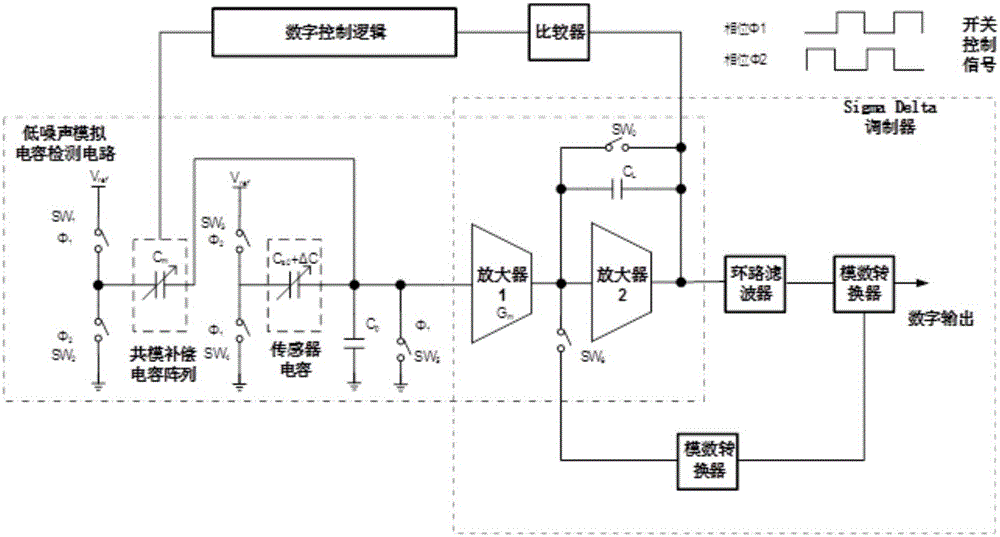
[0062] see Figure 3 to Figure 6 , The invention discloses a capacitance detection circuit, the capacitance detection circuit includes a low-noise analog capacitance detection circuit, a common-mode signal compensation capacitance, a self-calibration circuit, and the capacitance detection circuit is connected with a sigmadelta modulator.
[0063] The low-noise analog capacitance detection circuit is used to detect the capacitance of the MEMS structure (of course, it can also be other capacitive sensors, and the low-noise analog capacitance detection circuit can be used to detect other capacitive sensors).
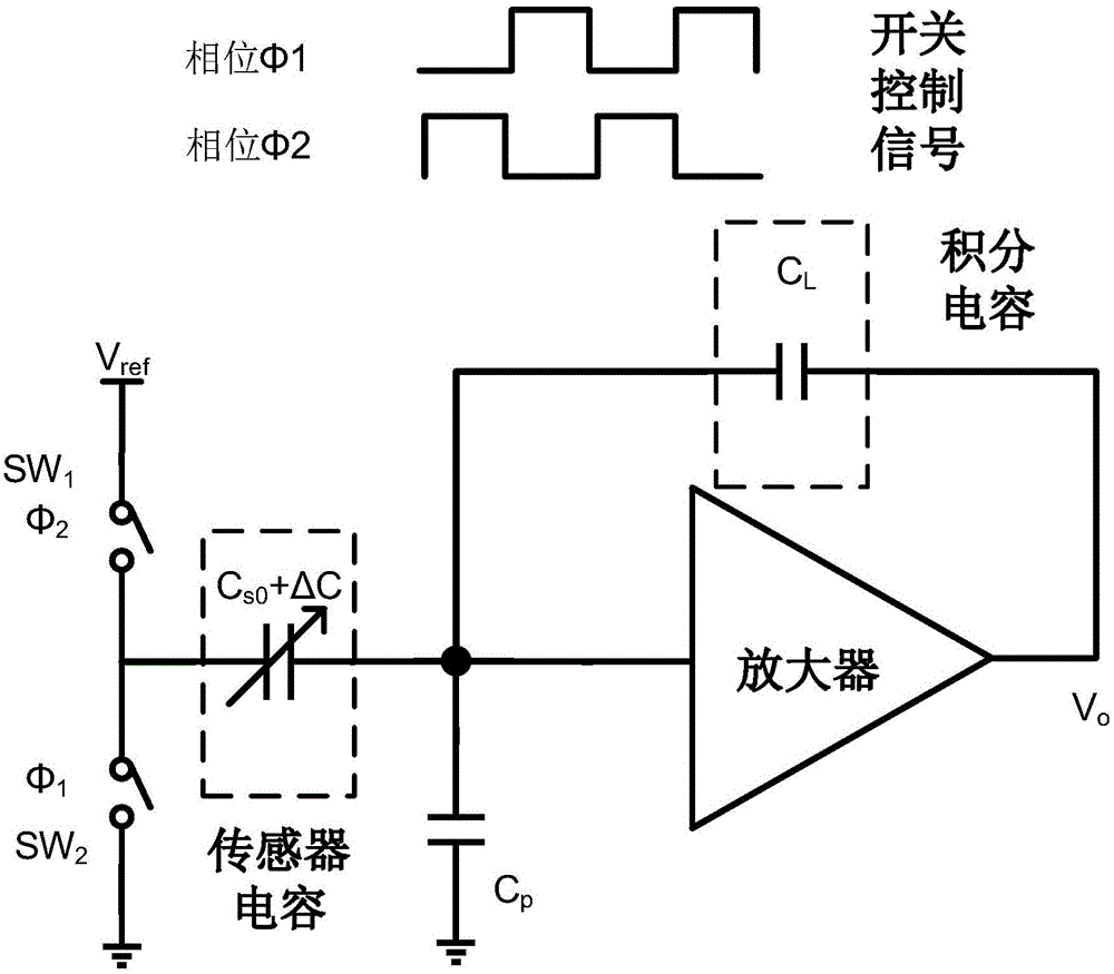
[0064] The low-noise analog capacitance-sensing circuit consists of a common-mode compensation capacitor C m , sensor capacitance C s0 and ΔC and switch SW 0 ~SW 5 A switched capacitor circuit consisting of a first amplifier, a second amplifier, and an amplifying capacitor C L and switch SW 0 A transconductance capacitor amplifier composed of; finally forming an amplif...
Embodiment 2
[0076] A capacitance detection circuit includes a low-noise analog capacitance detection circuit, a common-mode signal compensation capacitance, and a self-calibration circuit.
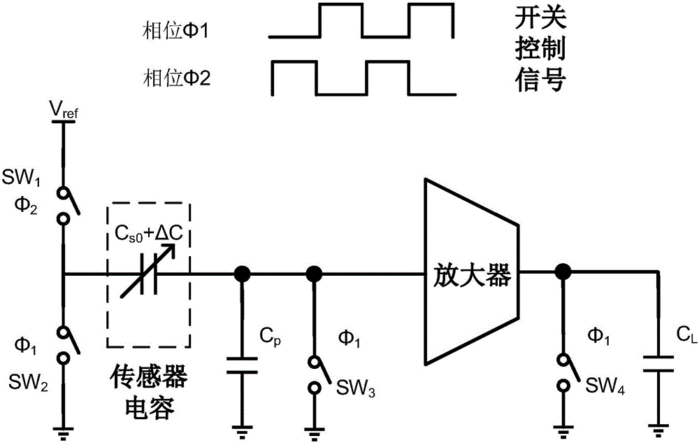
[0077] The low-noise analog capacitance detection circuit is used to detect capacitance (such as the capacitance of MEMS structure), such as Figure 4 shown.
[0078] The self-calibration circuit is connected with the common-mode signal compensation capacitor to compensate the change of the common-mode voltage of the low-noise analog capacitance detection circuit itself; the common-mode signal compensation capacitor is automatically found by the self-calibration circuit when the MEMS inspection circuit is started. capacitive balance point to compensate for changes in common-mode voltage, such as Figure 5 shown.
[0079] By adding a common-mode compensation capacitor, the common-mode variation at the input of the first amplifier is reduced to: The low frequency gain will be increased to: ...
Embodiment 3
[0091] A capacitance sensing circuit includes a low-noise analog capacitance detection circuit, a common-mode signal compensation capacitance, a self-calibration circuit and a sigmadelta modulator.
[0092] The low-noise analog capacitance detection circuit is used to detect the capacitance of the MEMS structure (also can be used to detect other capacitance sensors), such as Figure 4 shown.
[0093] The self-calibration circuit is connected with a common-mode signal compensation capacitor to compensate for the variation of the common-mode voltage of the low-noise analog capacitance detection circuit itself; when the MEMS inspection circuit is started, the self-calibration circuit automatically finds a capacitance balance point to compensate The change in common-mode voltage; the common-mode change at the input of the first amplifier is reduced to: The low frequency gain will be increased to: G 0 = G ...
PUM
 Abstract
Description
Claims
Application Information
 - R&D
- Intellectual Property
- Life Sciences
- Materials
- Tech Scout
- Unparalleled Data Quality
- Higher Quality Content
- 60% Fewer Hallucinations
Browse by: Latest US Patents, China's latest patents, Technical Efficacy Thesaurus, Application Domain, Technology Topic, Popular Technical Reports.
© 2025 PatSnap. All rights reserved.Legal|Privacy policy|Modern Slavery Act Transparency Statement|Sitemap|About US| Contact US: help@patsnap.com