Four-arm helical antenna of novel feed structure

A four-armed helix, a new type of technology, applied in the direction of the radiating element structure and the connection of the antenna grounding switch structure, can solve the problems of reducing the size of the antenna, restricting the application, etc., to reduce the overall size, improve the qualification rate, and achieve excellent performance. Effect

Active Publication Date: 2015-12-02
SEMITEL ELECTRONICS
View PDF6 Cites 6 Cited by
  • Summary
  • Abstract
  • Description
  • Claims
  • Application Information

AI Technical Summary

Problems solved by technology

This antenna is considered to be the most ideal positioning receiving antenna, but its large size has always restricted its application on small receiving equipment. After using dielectric loading, the antenna size is significantly reduced, and it has been continuously used in high-end positioning equipment in recent years.

Method used


Image

  • Four-arm helical antenna of novel feed structure
  • Four-arm helical antenna of novel feed structure
  • Four-arm helical antenna of novel feed structure

Examples


Embodiment 1

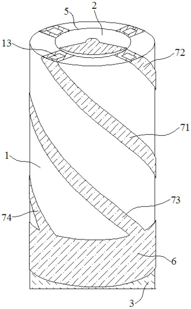
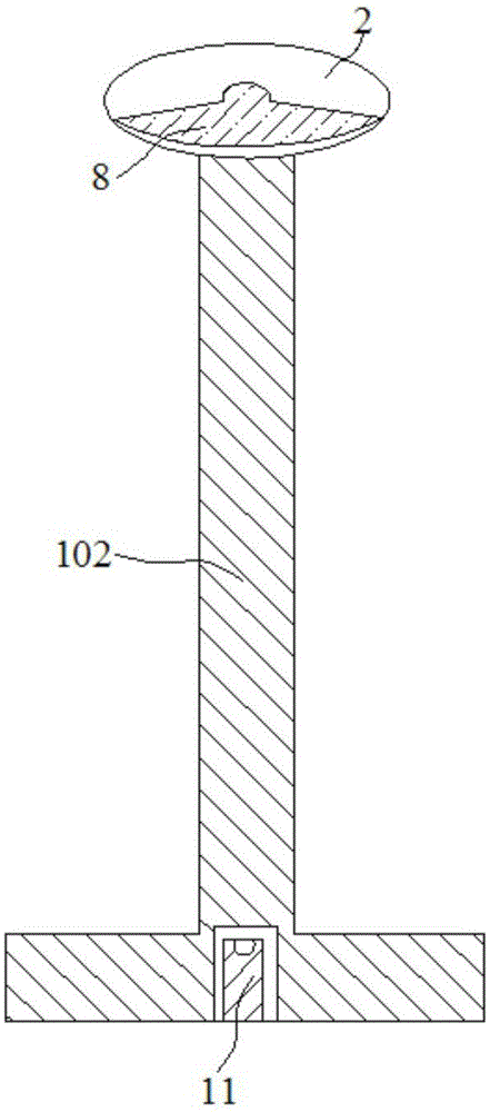
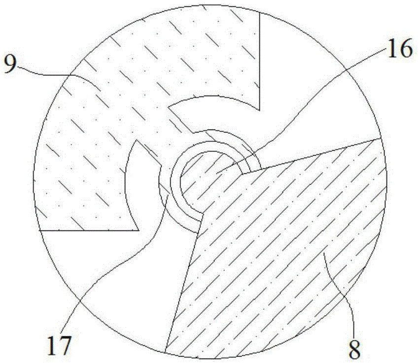
[0035] Embodiment 1: A four-arm helical antenna with a new feed structure, including a ceramic cylinder 1 with a through hole 5 at the axis, an upper PCB printed circuit board 2, a lower PCB printed circuit board 3 and a PCB printed connection board 4, The upper PCB printed circuit board 2 and the lower PCB printed circuit board 3 are respectively located in the upper opening and the lower part of the through hole 5, and the PCB printed connection board 4 is located in the through hole 5 of the ceramic cylinder 1 and is located on the upper PCB printed circuit board. 2. Between the lower PCB printed circuit board 3;

[0036] The lower part of the outer surface of the ceramic cylinder 1 has a Balun line 6 along the circumferential direction, and four metal spiral arms 7 are wound on the outer surface of the ceramic cylinder 1 at intervals, and the upper ends of the four metal spiral arms 7 extend to the ceramic cylinder 1. On the upper end surface of the ceramic cylinder 1, a m...

Embodiment 2

[0045] Embodiment 2: A four-arm helical antenna with a new feeding structure, including a ceramic cylinder 1 with a through hole 5 at the axis, an upper PCB printed circuit board 2, a lower PCB printed circuit board 3 and a PCB printed connection board 4, The upper PCB printed circuit board 2 and the lower PCB printed circuit board 3 are respectively located in the upper opening and the lower part of the through hole 5, and the PCB printed connection board 4 is located in the through hole 5 of the ceramic cylinder 1 and is located on the upper PCB printed circuit board. 2. Between the lower PCB printed circuit board 3;

[0046] The lower part of the outer surface of the ceramic cylinder 1 has a Balun line 6 along the circumferential direction, and four metal spiral arms 7 are wound on the outer surface of the ceramic cylinder 1 at intervals, and the upper ends of the four metal spiral arms 7 extend to the ceramic cylinder 1. On the upper end surface of the ceramic cylinder 1, ...


PUM


Abstract

The invention discloses a four-arm helical antenna of a novel feed structure, which comprises a ceramic pillar, an upper printed circuit board (PCB), a lower PCB and a PCB printed connection board. The axis of the ceramic pillar is provided with a through hole. The lower part of the outer side surface of the ceramic pillar is provided with BALUN lines along the circumferential direction. Four metal helical arms are wound onto the outer side surface of the ceramic pillar at intervals. The upper surface and the lower surface of the upper PCB are respectively printed with a fan-shaped upper conductive layer and a fan-shaped lower conductive layer. The metal adjustment regions of the first and second metal helical arms of the four metal helical arms are electrically connected with the fan-shaped upper conductive layer through the welding process. The third and fourth metal helical arms of the four metal helical arms are coupled to the fan-shaped lower conductive layer. The front side surface of the PCB printed connection board is provided with a grounding metal region and an input end region at the upper part of the PCB printed connection board. The fan-shaped lower conductive layer is electrically connected with the grounding metal region of the PCB printed connection board. According to the invention, the return loss is smaller than -25 dB, and the vertex gain is greater than -2 dB. Therefore, the overall size of an antenna is effectively reduced, and the antenna is good in circularly-polarized performance.

Description

technical field [0001] The invention relates to a four-arm helical antenna, in particular to a four-arm helical antenna with a novel feeding structure. Background technique [0002] As the key equipment for radio applications, antennas develop with the development of communication, broadcasting, radar and positioning light radio application systems. In recent years, the popularity of GPS and Beidou has made their applications in vehicle navigation and mobile terminals more and more widely. [0003] The concept of the four-arm helical antenna was first proposed by C.C.Kilgus in 1968. He analyzed the half-wavelength resonant four-arm helical antenna with the ring dipole model, and obtained the cardioid pattern and the hemispherical coverage of the four-arm helical antenna. Excellent circular polarization characteristics. This antenna is considered to be the most ideal positioning receiving antenna, but its large size has always restricted its application on small receiving e...

Claims


Application Information

Patent Timeline
Patent Type & Authority Applications(China)
IPC IPC(8): H01Q1/38H01Q1/50
Inventor 李凯冯波戴剑仇利民
Owner SEMITEL ELECTRONICS
Why Eureka
Try Eureka