X capacitor discharge control circuit used in switching power supply

A technology for controlling circuit and capacitor discharge, applied to electrical components, output power conversion devices, etc., can solve the problems of increasing no-load loss of power supply and greater impact on no-load efficiency of power supply

Active Publication Date: 2015-12-02
SILERGY SEMICON TECH (HANGZHOU) CO LTD
View PDF6 Cites 13 Cited by
  • Summary
  • Abstract
  • Description
  • Claims
  • Application Information

AI Technical Summary

Problems solved by technology

However, in this solution, since the discharge resistor is always connected in parallel at both ends of the X capacitor, when the switching power supply is in no-load mode, the loss generated on the discharge resistor will significantly increase the no-load loss of the power supply, which has a greater impact on the no-load efficiency of the power supply. In the context of increasingly stringent standby power consumption requirements for switching power supplies, traditional solutions can no longer meet the latest energy consumption requirements

Method used


Image

  • X capacitor discharge control circuit used in switching power supply
  • X capacitor discharge control circuit used in switching power supply
  • X capacitor discharge control circuit used in switching power supply

Examples


Embodiment Construction

[0038] Several preferred embodiments of the present invention will be described in detail below with reference to the accompanying drawings, but the present invention is not limited to these embodiments. The present invention covers any alternatives, modifications, equivalent methods and schemes made on the spirit and scope of the present invention. In order to provide the public with a thorough understanding of the present invention, specific details are set forth in the following preferred embodiments of the present invention, but those skilled in the art can fully understand the present invention without the description of these details.

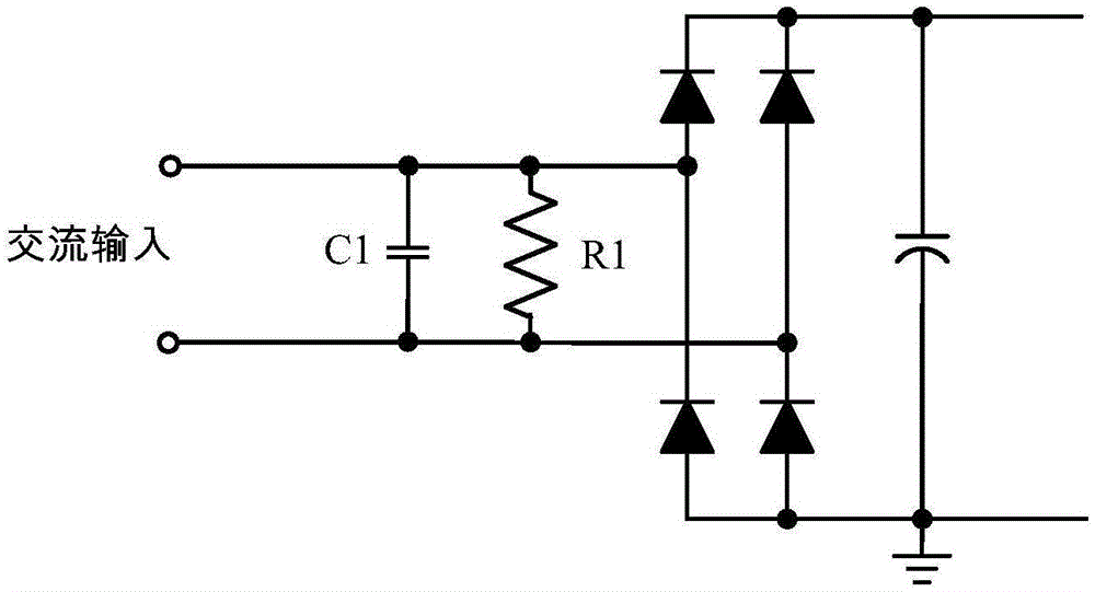
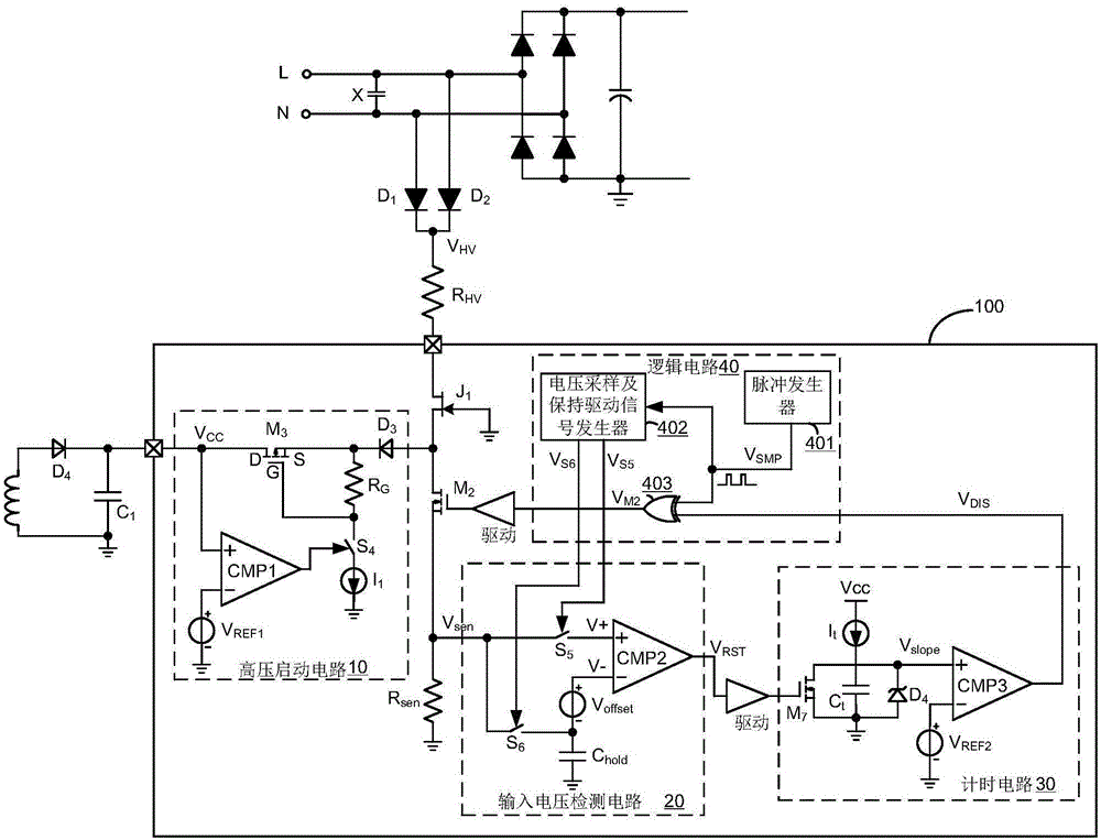
[0039] refer to figure 2 Shown is an X capacitor discharge control circuit applied in a switching power supply according to the present invention, the switching power supply includes an X capacitor connected between the input terminals of the switching power supply, such as figure 2 As shown, the X capacitor is connected between the ne...


PUM


Abstract

The invention discloses an X capacitor discharge control circuit used in a switching power supply. An X capacitor is discharged by a switching circuit formed by a depletion transistor and a second switching tube. Currently-sampled input voltage information is compared with input voltage information sampled and held in the last cycle and whether an input end is powered down is determined according to a compared result. When power down happens, the second switching tube is controlled to be switched on in order to discharge the X capacitor. In another aspect, the depletion transistor can be multiplexed in order that a power supply capacitor is charged by input-end voltage, thereby achieving high-voltage quick start of the control chip of the switching power supply.

Description

technical field [0001] The invention relates to the field of switching power supplies, and more specifically relates to an X capacitor discharge control circuit applied in switching power supplies. Background technique [0002] In an AC / DC switching power supply, in order to solve the EMI problem of electromagnetic interference, an EMI filter circuit is generally installed at the input end, and the filter circuit generally includes an X filter capacitor connected in parallel between the live line and the neutral line at the input end of the AC power supply. When the AC power at the input end of the AC / DC switching power supply is disconnected, a certain voltage will remain on the X filter capacitor. If a person touches the input electrode of the switching power supply, the residual voltage on the X filter capacitor may cause electric shock and hurt people. . Therefore, it is stipulated in the safety standard that when the switching power supply is disconnected from the inpu...

Claims


Application Information

Patent Timeline
Patent Type & Authority Applications(China)
IPC IPC(8): H02M1/32
Inventor 杨笑宇白永江董晋平
Owner SILERGY SEMICON TECH (HANGZHOU) CO LTD
Why Eureka
Try Eureka