Charge pump circuit

A charge pump and circuit technology, applied in the field of circuits, can solve the problems of unstable output voltage and waste of power consumption, and achieve the effect of stable output voltage and reduced waste of power consumption

Active Publication Date: 2015-12-02
GIGADEVICE SEMICON (BEIJING) INC
View PDF6 Cites 2 Cited by
  • Summary
  • Abstract
  • Description
  • Claims
  • Application Information

AI Technical Summary

Problems solved by technology

Every time the output voltage is detected, the current will be drawn from the output voltage terminal. If the output voltage is detected frequently, it will cause a lot of waste of power consumption. However, if the output voltage is detected every long time, the output voltage will be low. Will deviate greatly from the target voltage, making the output voltage very unstable

Method used


Image

  • Charge pump circuit
  • Charge pump circuit
  • Charge pump circuit

Examples


Embodiment 1

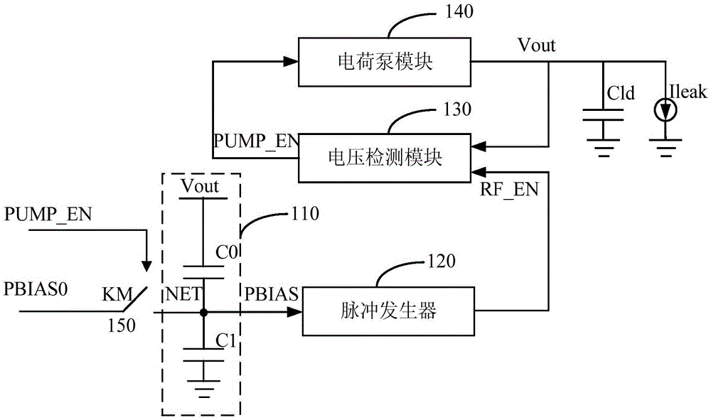
[0017] figure 1 This is a block diagram of a charge pump circuit provided in the first embodiment of the present invention. This embodiment is suitable for low-power integrated circuits. A block diagram of a charge pump circuit provided in this embodiment, such as figure 1 As shown, it includes: an output voltage monitoring module 110 for real-time monitoring of the output voltage of the charge pump and adjusting the reference voltage of the pulse generator; a pulse generator 120 for generating a pulse signal that changes in proportion to the reference voltage to the voltage Detection module; voltage detection module 130, used to detect the output voltage of the charge pump under the control of the pulse signal, and output an enable signal to the charge pump module, start the charge pump to start working; charge pump module 140, in the The target voltage is output under the control of the enable signal; the refresh frequency control switch 150 is used to set the reference voltag...

Embodiment 2

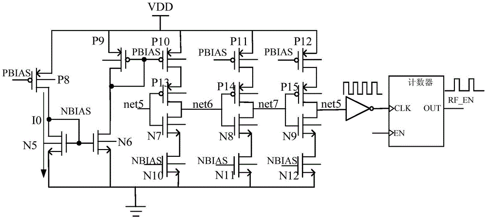
[0024] On the basis of the foregoing embodiment, in order to more clearly describe the working process of the pulse generator, as a preferred embodiment, image 3 The specific circuit diagram of the pulse generator is given, such as image 3 Shown: the pulse generator includes a ring oscillator and a counter, the ring oscillator and the counter are connected through an inverter;

[0025] Wherein, the ring oscillator includes a fifth NMOS tube, a sixth NMOS tube, a seventh NMOS tube, an eighth NMOS tube, a ninth NMOS tube, a tenth NMOS tube, an eleventh NMOS tube, and a twelfth NMOS tube. , Eighth PMOS, Ninth PMOS, Tenth PMOS, Eleventh PMOS, Twelfth PMOS, Thirteenth PMOS, Fourteenth PMOS, and Fifteenth PMOS;

[0026] The gate of the eighth PMOS transistor is the reference voltage input terminal of the pulse generator and is connected to the output voltage monitoring module, the source is connected to the power terminal, and the drain is connected to the drain of the fifth NMOS tran...


PUM


Abstract

The invention discloses a charge pump circuit. The charge pump circuit comprises the following components that: an output voltage monitoring module used for monitoring the output voltage of a charge pump in real time and adjusting the reference voltage of a pulse generator; the pulse generator which is used for generating pulse signals which change with the reference voltage in a directly proportional manner to a voltage detection module; the voltage detection module used for detecting the output voltage of the charge pump under the control of the pulse signals and outputting enabling signals to a charge pump module to start the charge pump, so that the charge pump can begin to work; the charge pump module which outputs target voltage under the control of the enabling signals; and a refresh frequency control switch which is used for setting the reference voltage of the pulse generator as initial reference voltage when refresh is carried out every time. According to the charge pump circuit provided by the embodiment of the invention, the pulse frequency of the pulse generator is adjusted according to output voltage monitoring results, so that refresh self adjustment can be performed on the detection frequency of the voltage detection module, and therefore, the waste of power dissipation can be reduced to the largest extent with the stability of the output voltage ensured.

Description

Technical field [0001] The embodiments of the present invention relate to the technical field of circuits, and in particular to a charge pump circuit. Background technique [0002] As the basic module of Flash memory, charge pump circuit largely determines the programming / erasing speed of Flash. With the continuous development of integrated circuits, based on the consideration of low power consumption and low cost, charge pump circuits are more and more widely used in integrated circuits. [0003] The basic working principle of the charge pump is to raise the output voltage of the charge pump through the accumulation effect of the capacitor on the charge. Due to the leakage current, the charge pump needs a detection circuit to detect the output voltage. When the output voltage is lower than the target voltage, the charge pump starts to work to raise the output voltage to the target voltage. Each pair of output voltage detection will draw current from the output voltage terminal. ...

Claims


Application Information

Patent Timeline
IPC IPC(8): H02M3/07
Inventor 陈晓璐
Owner GIGADEVICE SEMICON (BEIJING) INC
Why Eureka
Try Eureka