Compressor comprising cylinder head

A compressor and cylinder head technology, applied in the field of compressors, can solve problems such as compressor efficiency and adverse effects on performance, and achieve the effect of increasing efficiency and preventing heat transfer

Inactive Publication Date: 2015-12-02
ARCELIK AS
View PDF7 Cites 0 Cited by
  • Summary
  • Abstract
  • Description
  • Claims
  • Application Information

AI Technical Summary

Problems solved by technology

As a result, the efficiency and performa...

Method used


Image

  • Compressor comprising cylinder head
  • Compressor comprising cylinder head
  • Compressor comprising cylinder head

Examples


Embodiment Construction

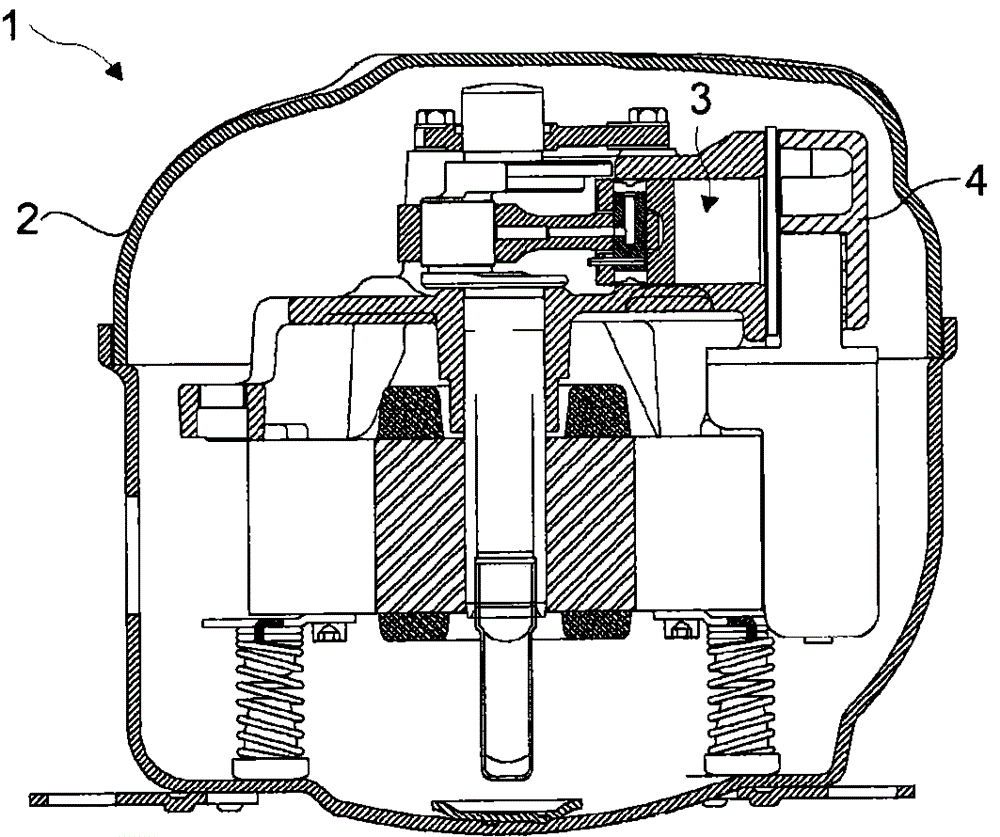
[0031] The compressor (1) consists of a housing (2) in which the elements are carried, a cylinder (3) in which the compression process is carried out, a cylinder head (4) placed on the cylinder (3), placed under the cylinder head (4) At least one discharge chamber (5) filled with the pumped circulating fluid, and at least one suction chamber (6) filled with the suctioned circulating fluid ( figure 1 ).

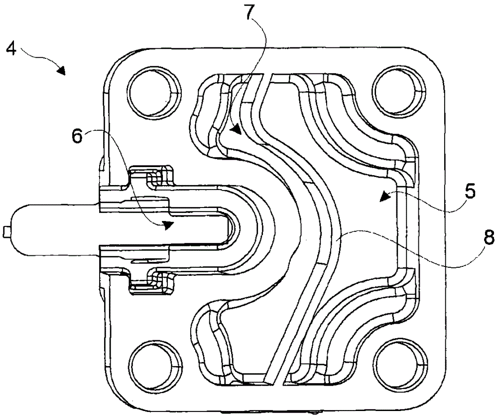
[0032] The compressor (1) of the invention comprises at least one vacuum-isolated chamber (7), located on the cylinder head (4), between the suction chamber (6) and the discharge chamber (5). During the production process of the compressor (1), the inside of the compressor is evacuated to dehumidify. At the same time, the interior of the chamber (7) is also evacuated. The isolation efficiency of the vacuumed chamber (7) is increased ( figure 2 ).

[0033] During operation of the compressor (1), the temperature of the refrigerant compressed inside the cylinder (3) increase...


PUM


Abstract

The present invention relates to a compressor (1) comprising a casing (2) carrying the components therein, a cylinder (3) wherein the compression process is performed, a cylinder head (4) disposed on the cylinder (3), at least one exhaust chamber (5) disposed at the cylinder head (4), wherein the pumped circulating fluid fills and at least one suction chamber (6) wherein the sucked circulating fluid fills.

Description

technical field [0001] The invention relates to a compressor comprising a cylinder head for use in a cooling plant. Background technique [0002] In hermetic compressors used in domestic refrigerators, the refrigerant passes through the muffler and suction chamber of the cylinder head to the cylinder. At the end of the compression process, the refrigerant having increased pressure and temperature is discharged to the discharge chamber of the cylinder head after leaving the cylinder. The refrigerant compressed in the cylinder and transferred to the discharge chamber raises the temperature inside the suction chamber. An increase in temperature in the discharge chamber also causes an increase in temperature in the suction chamber. As a result, the efficiency and performance of the compressor can be adversely affected. [0003] In the prior art US patent document US20050226740 a compressor is disclosed which has an isolated cavity which is located between the suction cavity a...

Claims


Application Information

Patent Timeline
IPC IPC(8): F04B27/10F04B39/12
CPCF04B27/1081F04B39/125
Inventor C·萨欣E·奥古兹A·R·奥兹德米A·B·托普
Owner ARCELIK AS
Why Eureka
Try Eureka