Bending machine and operation method thereof

A bending machine and frame technology, applied in the field of bending machines, can solve the problems of time-consuming and laborious adjustment, increase the production cost, affect the rigidity of the machine, etc., and achieve the effect of simple operation method, easy implementation and simplified overall structure.

Active Publication Date: 2015-12-09
GUANGZHOU SHIPYARD INTERNATIONAL LTD
View PDF4 Cites 2 Cited by
  • Summary
  • Abstract
  • Description
  • Claims
  • Application Information

AI Technical Summary

Problems solved by technology

Since the deflection of the slider is a parabolic curve, and the bending force of the bending machine changes, the compensation amount will change with the change of the working force. The table deflection compensation mechanism for adjusting the wedge method requires multiple sets of wedges. In order to make the compensation curve smooth, the adjustment is time-consuming and laborious, the production cost is also high, and the effect is not ideal in practical applications; the compensation amount of the method of installing a compensation cylinder built into the support plate of the workbench can be controlled by the hydraulic system, and the compensation amount can follow the working force. However, this method needs to set up an independent compensation cylinder, which increases the production cost, and the workbench support plate must be designed as a three-piece split structure, which seriously affects the rigidity of the machine

Method used


Image

  • Bending machine and operation method thereof
  • Bending machine and operation method thereof
  • Bending machine and operation method thereof

Examples


Embodiment 1

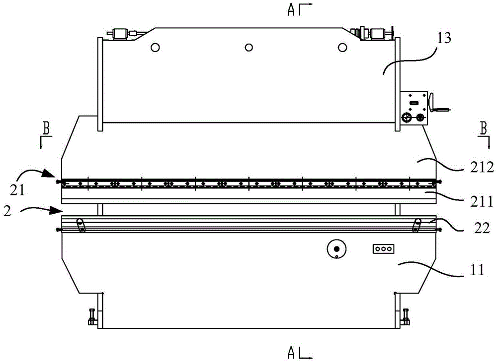
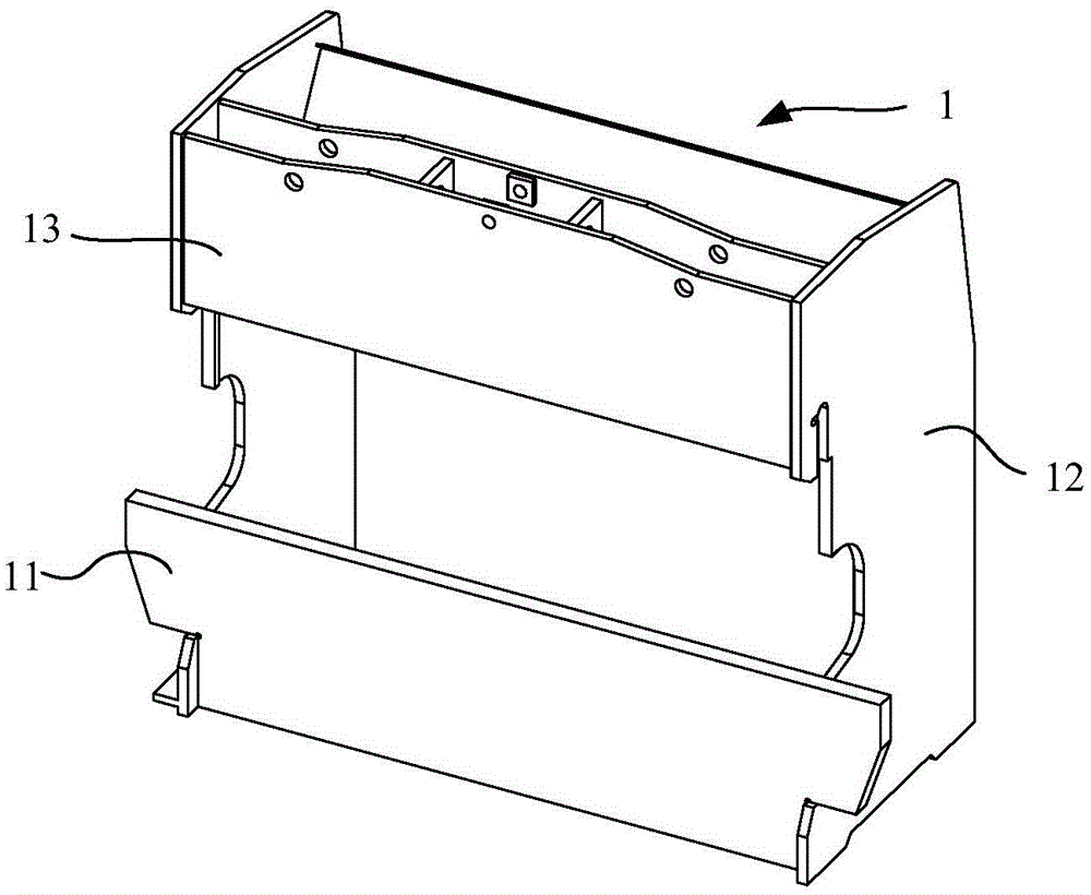
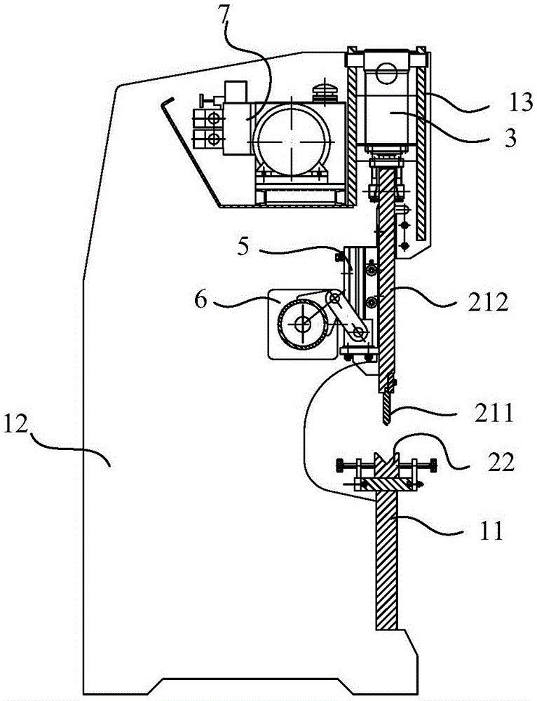
[0040] Such as figure 1 As shown, a bending machine includes a frame 1 and a mold 2 arranged on the frame 1, such as figure 2 As shown, the frame 1 includes a workbench 11, side panels 12 and top beams 13, as image 3 As shown, the mold 2 includes an upper mold 21 and a lower mold 22 that cooperate with each other, the lower mold 22 is fixed on the workbench 11, and three oil cylinders 3 are arranged above the upper mold 21, as Figure 4 As shown, three oil cylinders 3 are fixed on the top crossbeam 13, and the upper mold body 21 includes an upper mold body 211 and a slider 212, and the upper mold body 211 is detachably fixed on the lower end of the slider 212, so that it is convenient to replace and maintain the upper mold body 211 separately The three oil cylinders 3 are arranged above the slide block 212, the piston rods 31 of the three oil cylinders 3 are all connected with the slide block 212, and the force on the slide block 212 is even, so that the bending straightnes...

Embodiment 2

[0048] The bending machine of this embodiment has the same basic structure as that of Embodiment 1, including a frame 1 and a mold 2 arranged on the frame 1. The mold 2 includes an upper mold 21 and a lower mold 22 that cooperate with each other. Three oil cylinders 3 are provided, and the three oil cylinders 3 apply the same force to the upper die 21 .

[0049] The difference from Embodiment 1 is that the specific structure of the frame 1 is not limited, the specific structure of the upper mold 21 and the lower mold 22 is not limited, as long as the bending can be realized, and the number of the oil cylinders 3 is not limited, it can be the upper mold 21 provides power and can realize deflection compensation to the workpiece.

Embodiment 3

[0051] The operation method of the bending machine is as follows: first, bend the workpiece through the mold 2; secondly, perform deflection compensation on the workpiece: when the upper die 21 goes down to the bottom dead center to complete the bending of the workpiece, continue to control the oil cylinder 3 The output force can make the middle part of the upper mold 21 convex and deformed, and the deformation in the middle of the upper mold 21 just offsets the deformation of the lower mold 22 and the worktable 11 supporting the lower mold 22 under the force, as Figure 9 and 10 shown. The factors affecting the deformation of the upper mold 21 are the stiffness of the frame 1 and the output force of the cylinder 3, and the output force of the cylinder 3 changes with the bending force of the workpiece, so the material of the workpiece determines the output of the cylinder 3. The output force of the oil cylinder 3 determines the deformation of the upper die 21; therefore, the ...


PUM


Abstract

The invention discloses a bending machine and an operation method thereof, and relates to the technical field of bending machines. The bending machine comprises a machine frame and a die arranged on the machine frame. The die comprises an upper die body and a lower die body which are matched with each other. Oil cylinders are arranged above the upper die body, can provide power for the upper die body, and can make the lower die body achieve flexibility compensation. The operation method includes the step that after the upper die body runs downwards to a lower stop point and completes workpiece bending, the three oil cylinders continue to be controlled to conduct output so that the middle of the upper die body can protrude downwards and deform, wherein the deformation amount of the middle of the upper die body can just offset the deformation amount generated when the lower die body bears force and is indented downwards. The bending machine and the operation method of the bending machine can solve the problems that in the past, the bending linearity is low and automatic flexibility compensation can not be achieved.

Description

technical field [0001] The invention relates to the technical field of bending machines, in particular to a bending machine and an operating method thereof. Background technique [0002] Bending machine is a processing machine that bends sheet metal in a straight line in a cold state. Most of the current bending machines have a two-cylinder structure, which consists of a frame, left and right cylinders, sliders, upper molds, and lower molds. The frame is composed of left and right side plates and a workbench, the workbench is used to support the lower mold, and the left and right side plates are used to install the oil cylinder; the piston rod of the oil cylinder is connected with the slider, which drives the slider to move up and down, so that it is installed on the slider The upper mold on the upper side is pressed into the lower mold to complete the sheet metal bending work. The mold of the bending machine is narrow and long, and the length is mostly 3-4 meters, even as ...

Claims


Application Information

Patent Timeline
Patent Type & Authority Applications(China)
IPC IPC(8): B21D5/06
Inventor 陈尚贵黎召军李志丹郑升发
Owner GUANGZHOU SHIPYARD INTERNATIONAL LTD
Why Eureka
Try Eureka