Wire drawing machine and wire drawing technology for automobile stepping bar surface wire drawing treatment

A technology of surface drawing and drawing machine, which is applied in the direction of machine tools, manufacturing tools, and grinding workpiece supports suitable for grinding workpiece planes. It can solve the problems of unstable drawing effect, low efficiency, and no guarantee of drawing quality. Convenient card, good interlocking, reliable clamping effect

Active Publication Date: 2015-12-09
SHANXI KAMEITE IND MACHINERY CO LTD
View PDF6 Cites 15 Cited by
  • Summary
  • Abstract
  • Description
  • Claims
  • Application Information

AI Technical Summary

Problems solved by technology

[0003] The present invention mainly aims at the problems of unstable drawing effect, unguaranteed drawing quality and low efficiency in

Method used


Image

  • Wire drawing machine and wire drawing technology for automobile stepping bar surface wire drawing treatment
  • Wire drawing machine and wire drawing technology for automobile stepping bar surface wire drawing treatment
  • Wire drawing machine and wire drawing technology for automobile stepping bar surface wire drawing treatment

Examples


Embodiment 1

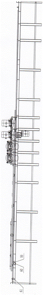
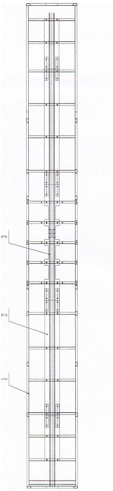
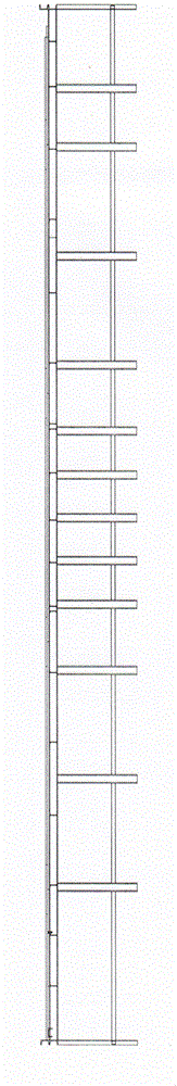
[0040] A wire drawing machine used for wire drawing treatment on the surface of automobile step bars, such as figure 1 As shown, it is composed of a workbench, tooling clamping mechanism, feed transmission mechanism, wire drawing mechanism, limit mechanism, circuit control and air circuit control, such as figure 2 and image 3 As shown, the workbench is composed of a frame 1, a work platform 2 and two transmission guide rails 3, the work platform 2 is arranged on the frame 1, and the two transmission guide rails 3 are arranged in the middle of the work platform 2 in parallel;

[0041] like Figure 4 As shown, the tooling clamping mechanism is composed of a clamping cylinder 4, an optical axis ejector rod 5, three linear bearings 6, a front clamping block 7, a plurality of lever body fixing plates 8, a T-shaped chute 9, and a plurality of T Type slider 10 and rear clamping block 11, the clamping cylinder 4 is connected with the leftmost T-shaped slider 10 through a bar body ...


PUM


Abstract

The invention belongs to the technical field of wire drawing machines, particularly relates to a wire drawing machine and wire drawing technology for automobile stepping bar surface wire drawing treatment, and mainly solves the problems that the conventional wire drawing machine is unstable in wire drawing effect and low in efficiency and the wire drawing quality is not guaranteed. The wire drawing machine for automobile stepping bar surface wire drawing treatment comprise a workbench, a tool clamping mechanism, a feeding transmission mechanism, a wire drawing mechanism, a limiting mechanism, a circuit control part and a gas circuit control part, wherein the tool clamping mechanism comprises a clamping air cylinder, an optical axis ejector rod, three linear bearings, a front clamping block, a plurality of rod body fixing plates, a T-shaped sliding groove, a plurality of T-shaped sliding blocks and a back clamping block; the wire drawing mechanism comprises a lateral wire drawing part and a chamfer wire drawing part; the lateral wire drawing part comprises two working stations; two lateral wire drawing mechanisms are symmetrically mounted on each working station; the chamfer wire drawing part also comprises two working stations; two chamfer wire drawing mechanisms are symmetrically mounted on each working station.

Description

technical field [0001] The invention relates to a wire-drawing machine and a wire-drawing process used for wire-drawing treatment on the surface of an automobile step bar. Background technique [0002] At present, the conventional wire drawing machine generally uses rollers to rely on friction transmission to realize the feeding of the workpiece. The pressure of wire drawing is controlled by a screw. With the wear of the wire drawing wheel, the pressure of wire drawing changes, which will make the effect of wire drawing unstable. , the quality of wire drawing cannot be guaranteed, and because some manufacturers have low manufacturing precision and the transmission process is not very stable, it may cause some lateral movement of the workpiece, so that some vibration lines will be generated during the wire drawing process, which will greatly reduce the effect of wire drawing . Moreover, during the wire drawing process, there is a lot of dust, which must be adsorbed on the su...

Claims


Application Information

Patent Timeline
IPC IPC(8): B24B7/10B24B27/00B24B41/06
CPCB24B7/10B24B27/0023B24B41/06
Inventor 郭勇慧
Owner SHANXI KAMEITE IND MACHINERY CO LTD
Why Eureka
Try Eureka