
Clamp used for tool wear detection

A tool wear and tool technology, which is applied in the field of tool detection equipment, can solve the problems of inability to complete all-round detection of tool wear and poor versatility of the device, and achieve the effect of convenient operation and simple fixture structure

Active Publication Date: 2015-12-09
DALIAN UNIV OF TECH
View PDF9 Cites 15 Cited by
  • Summary
  • Abstract
  • Description
  • Claims
  • Application Information

AI Technical Summary

Problems solved by technology

[0004] The technical problem to be solved by the present invention is to overcome the defects of poor versatility of existing devices, the inability to realize translation in the plane and rotation in three axis directions at the same time, and the inability to complete all-round detection of tool wear, and to invent a tool for tool wear Inspection Fixture

Method used


Image

  • Clamp used for tool wear detection
  • Clamp used for tool wear detection
  • Clamp used for tool wear detection

Examples


Embodiment Construction

[0014] The specific implementation of the present invention will be described in detail below in conjunction with the accompanying drawings and technical solutions.

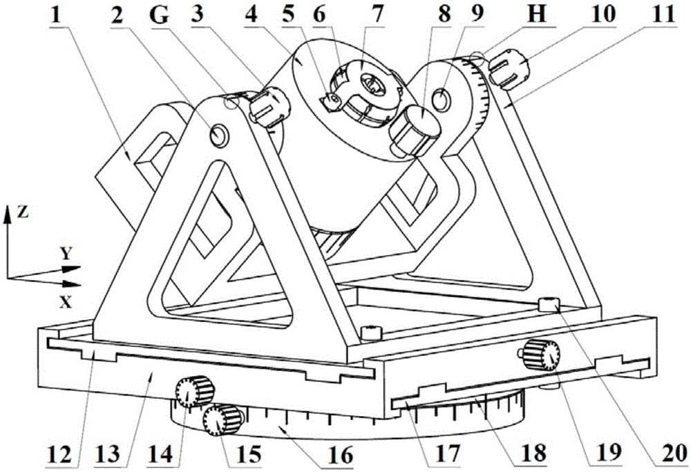
[0015] The embodiment is to manually realize the small-scale translational movement of the displacement table in the X and Y planes and the rotation of the three rotating mechanisms in the three axis directions, and use the tool chuck to realize the precise positioning and clamping of the tool. The specific structure of the fixture is as figure 1 As shown, the turntable assembly is installed under the lower displacement plate 17 of the workbench in the displacement workbench assembly through the turntable bolt 21, and the bracket assembly is installed on the upper displacement plate 12 of the workbench in the displacement workbench assembly through 4 support bolts 20. The clamping assembly is installed on the bracket 11 in the bracket assembly through the left and right pin shafts 2 and 9; the shaft hole of the b...


PUM


Abstract

The invention provides a clamp used for tool wear detection, belongs to the field of tool detection devices, and relates to the clamp used for tool detection. The clamp is suitable for devices used for wear detection on tools for machining holes in carbon fiber reinforced composites. The clamp is composed of a tool clamping assembly, a support assembly, a rotating table assembly and a displacement working table assembly. A tool is accurately positioned and clamped through the tool clamping assembly. By means of the clamp, the small-range horizontal movement of a displacement working table in the X-Y plane is achieved in a manual mode, and rotation of three rotation assemblies in three axis directions is achieved in a manual mode. In the tool clamping assembly, a base is of a structure shaped like a Chinese character 'shan', a circular protrusion is arranged at the center of the base, circular holes are machined in the upper portions of the left side wall and the right side wall of the base respectively, annularly-carved base left side angle scales are formed in the top of the left side wall, and annularly-carved base right side angle scales are formed in the top of the right side wall. The clamp is simple in structure and convenient to operate, and the good measurement device is provided for accurate detection on tool wear.

Description

technical field [0001] The invention belongs to the field of tool detection equipment, and relates to a fixture for tool detection, which is especially suitable for a tool wear detection device for hole-making and machining of carbon fiber reinforced composite materials. Background technique [0002] At present, carbon fiber reinforced composite materials are widely used in the aerospace field to manufacture various structural parts due to their advantages of light weight and high specific strength. Due to the assembly requirements between structural parts, a large number of high-quality connections must be manufactured through machining. hole. However, carbon fiber is extremely abrasive, and the mechanical scratching during processing causes the Co binder in the cemented carbide tool to be damaged, and the leakage of the cemented carbide grain exacerbates the process of the tool body being peeled off. Rapid tool wear, manifested as cutting edge passivation and flank wear. ...

Claims


Application Information

Patent Timeline
IPC IPC(8): B25B11/00
CPCB25B11/00
Inventor 贾振元钱宝伟付饶王福吉何春伶
Owner DALIAN UNIV OF TECH
Learn More