
Electric power-assisted trolley

An electric power assist and trolley technology, applied in the field of trolleys, can solve the problems of high cost, complicated operation, easy failure, etc., and achieve the effect of saving precious time, high moving efficiency, and avoiding low efficiency.

Active Publication Date: 2015-12-09
YANSHAN UNIV
View PDF7 Cites 6 Cited by
  • Summary
  • Abstract
  • Description
  • Claims
  • Application Information

AI Technical Summary

Problems solved by technology

The operation of pure electric drive is more complicated, and it is difficult to achieve translation in any direction without changing the orientation of the equipment on the ground, and the cost of pure electric drive is high. The control system is complex and prone to failure; Physical requirements are high, and it is not suitable for long-distance movement, and the efficiency is low. It is not suitable for operating rooms where every second counts.

Method used


Image

  • Electric power-assisted trolley
  • Electric power-assisted trolley
  • Electric power-assisted trolley

Examples


Embodiment Construction

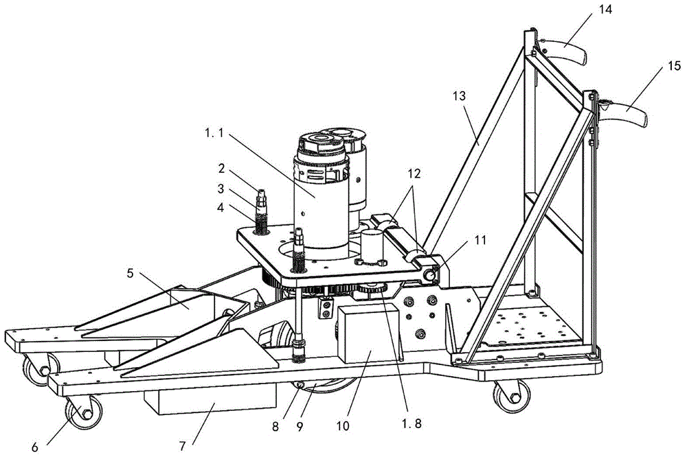
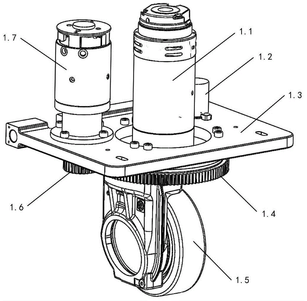
[0019] exist figure 1 In the schematic diagram of the electric power-assisted trolley shown, an oval through-hole is provided in the middle of the base 5, vertical ribs are respectively welded longitudinally on both sides of the through-hole, and universal wheels 6 are arranged at the bottom of the frame, respectively for the left front wheel , the right front wheel, the left rear wheel and the right rear wheel, the floor brake 21 is located at the middle part of the bottom rear end of the base, the battery 7 is located at the bottom of the base 5, and the control unit 10 is located at the base next to the rib plate on one side On the inside, the control unit 10 is integrated with a single-chip microcomputer, which processes the information input by the direction knob 16, the drive button and the encoder 1.2 and outputs it to the drive motor 1.1 and the steering motor 1.7;

[0020] The drive unit adopts the drive unit of model MRT23.D0002 purchased from the market. The drive u...


PUM


Abstract

An electric power-assisted trolley mainly comprises a base, a driving unit, a threaded pull rod, a battery, a control unit, universal wheels, a handrail frame, a right handle, a left handle, a direction knob and a driving button, wherein a through hole is formed in the middle of the base, rectangular vertical rib plates are welded to the two sides of the through hole respectively in the longitudinal direction, the universal wheels are arranged on the bottom of the base, and the battery is arranged on the bottom of the base; the control unit is arranged on the base and located beside the rectangular vertical rib plate on one side, the driving unit is arranged at the position of the through hole in the middle of the base, and the handrail frame is installed behind the base; the two handles are arranged at the upper end of the handrail frame, the left handle is provided with the direction knob which can rotate within the + / -90-degree range, and the forward driving button is arranged on the right handle. By the adoption of the trolley, the problem that middle-sized C-shaped arm X-ray machine equipment is complicated in operation and hard to move transversely in the purely motor driven mode is solved, and the defects of the purely manual driving mode that efficiency is low and the requirement for physical strength is high are overcome.

Description

technical field [0001] The invention relates to a trolley for medical C-arm X-ray equipment. Background technique [0002] With the advancement of science and technology, more and more advanced medical C-arm X-ray equipment has gradually entered the operating room of the ward, and the functions of medical equipment are becoming more and more powerful. Movement during use is increasingly difficult. Most of the driving devices of medium-sized medical C-arm X-ray equipment with a weight of about 1 ton are purely electric drives, and a small part are purely manual drives. The operation of pure electric drive is more complicated, and it is difficult to achieve translation in any direction without changing the orientation of the equipment on the ground, and the cost of pure electric drive is relatively high. The control system is complex and prone to failure; The physical requirements of personnel are high, and it is not suitable for long-distance movement. The efficiency is low...

Claims


Application Information

Patent Timeline
Patent Type & Authority Applications(China)
IPC IPC(8): B62B11/00
Inventor 曾达幸郜鹏张庆武侯雨雷
Owner YANSHAN UNIV
Learn More