
Take-up structure Microphone wire winding and automatic reset structure

An automatic reset, microphone wire technology, applied in the field of wire take-up structure, can solve the problems of stuck wire, microphone core wire breakage, large stress when the microphone wire is bent, etc., to achieve a good user experience, low friction, pulling and recycling Smooth process effect

Active Publication Date: 2017-03-01
HUNAN GREATWALL INFORMATION FINANCIAL EQUIP
View PDF9 Cites 0 Cited by
  • Summary
  • Abstract
  • Description
  • Claims
  • Application Information

AI Technical Summary

Problems solved by technology

However, due to the explosion-proof requirements of the microphone cable, the microphone cable is a metal single-hook structure and double-hook structure with grooves. When multiple microphone cables are interlaced, the friction between them is relatively large, and the stress of the microphone cable is large when it is bent. Difficult to draw and recover
[0003] When the microphone cable is recycled, due to the deformation and bending of the metal microphone cable, it is easy to be vertically overlapped and staggered by the second wire at the outlet of the barrel, causing the cable to be stuck, and the position restriction of the outlet port of the microphone stand cannot completely avoid recycling. Time stuck line problem
[0004] When the microphone cable is a PVC flat phone cable, the friction between the overlapping and winding microphone cables is small, and the microphone cable is pulled and recovered smoothly, but the PVC flat cable does not meet the explosion-proof requirements and is easily damaged by violence. It is easy to cause the core wire of the microphone to break during the pulling process

Method used


Image

  • Take-up structure Microphone wire winding and automatic reset structure
  • Take-up structure Microphone wire winding and automatic reset structure
  • Take-up structure Microphone wire winding and automatic reset structure

Examples


Embodiment Construction

[0047] The present invention will be further described below in conjunction with accompanying drawing.

[0048] The existing take-up structure microphone wire winding is:

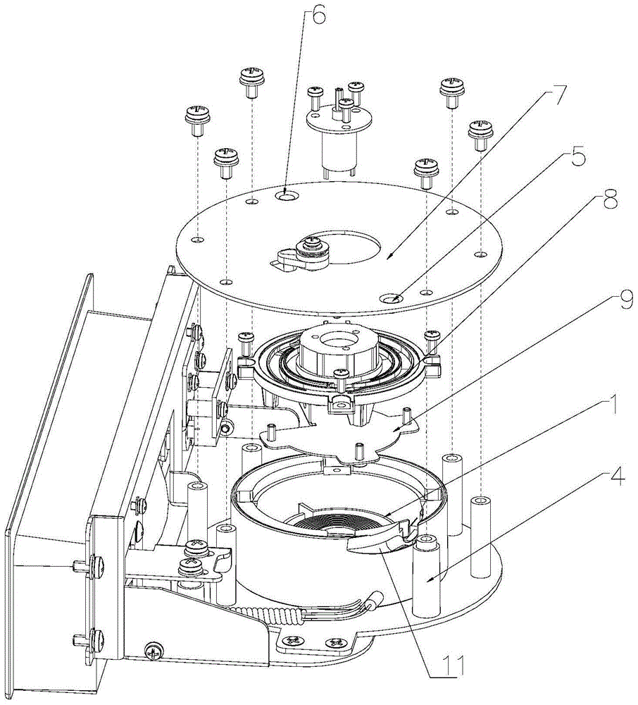
[0049] Figure 10 Shown: the microphone line of the telephone is connected to the outlet of the coil spring seat 1 through the coil spring seat upper cover 8 and the terminal on the internal conductive slip ring. And utilize the stainless steel pressing piece 12 to compress the connector on the coil spring seat 1.

[0050] This design has the following problems:

[0051] 1. The outlet position of the microphone line is at the upper position of the upper cover 8 of the coil spring seat, and the arrangement height of the microphone line is not enough, which may easily cause overlapping and staggering of the microphone line during the take-up process of the microphone line.

[0052]2. Since the coil spring seat 1 and the coil spring seat upper cover 8 are assembled, the height dimension is 28mm, the outer d...


PUM


Abstract

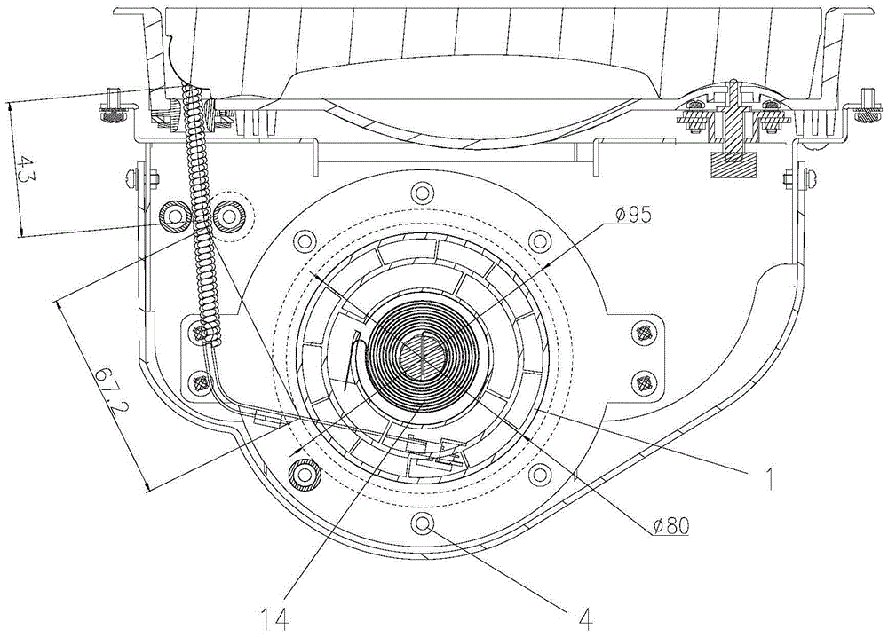
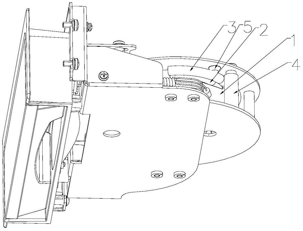
The invention discloses a cord winding and automatic resetting structure of a take-up structure microphone cord. The cord winding and automatic resetting structure comprises a take-up structure assembly and the microphone cord. The take-up structure assembly comprises a take-up structure upper plate (7), a going barrel and pressing rivet nut columns (4). The going barrel comprises a coil spring seat upper cover (8), a coil spring seat (1) and a microphone cord pressing sheet (9). A guide groove (11) is formed in the top of the coil spring seat (1). Only one microphone cord can be contained on the cross section between a circle formed by the pressing rivet nut columns around the coil spring seat (1) and a POM shaft sleeve (4) and the coil spring seat (1), wherein only the pressing rivet nut column at the cord outlet position of the take-up structure assembly is provided with the POM shaft sleeve. A first resetting convex hull (5) and a second resetting convex hull (6) are arranged on the side, facing the coil spring seat (1), of the take-up structure upper plate (7). According to the cord winding and automatic resetting structure of the take-up structure microphone cord, the microphone cord is prevented from being staggered or overlapped, the microphone cord is drawn, pulled and recycled smoothly when used by a user, and user experience is good.

Description

technical field [0001] The invention relates to a take-up structure of financial equipment, in particular to a winding and automatic reset structure of a microphone line of the self-locking and self-releasing structure of the financial equipment. Background technique [0002] In the existing self-locking and self-releasing structure of financial equipment, in order to meet the use requirements of users of different heights, the length of the microphone line is relatively long. The current common structure is that multiple rows of microphone lines are overlapped and wound on the barrel. However, due to the explosion-proof requirements of the microphone cable, the microphone cable is a metal single-hook structure and double-hook structure with grooves. When multiple microphone cables are interlaced, the friction between them is relatively large, and the stress of the microphone cable is large when it is bent. Pulling and recycling are difficult. [0003] When the microphone c...

Claims


Application Information

Patent Timeline
Patent Type & Authority Patents(China)
IPC IPC(8): B65H75/38B65H75/48
Inventor 闵红华李洪雷
Owner HUNAN GREATWALL INFORMATION FINANCIAL EQUIP
Learn More