
Aeration tine device

a technology of aeration tines and tines, which is applied in the direction of drags, lawn mowers, agriculture tools and machines, etc., can solve the problems of increasing the cost of aeration tines, so as to achieve adequate disposal of soil plugs, smooth operation, and excellent controllability

Inactive Publication Date: 2005-08-04
KASHIWATOOL CORP
View PDF14 Cites 7 Cited by
  • Summary
  • Abstract
  • Description
  • Claims
  • Application Information

AI Technical Summary

Benefits of technology

[0009] It is an object of the invention to provide an aeration tine device durable even where used for many number of turf sites. It is another object of the invention to provide an aeration tine device smoothly operational in having excellent controllability and adequately discarding soil plugs.
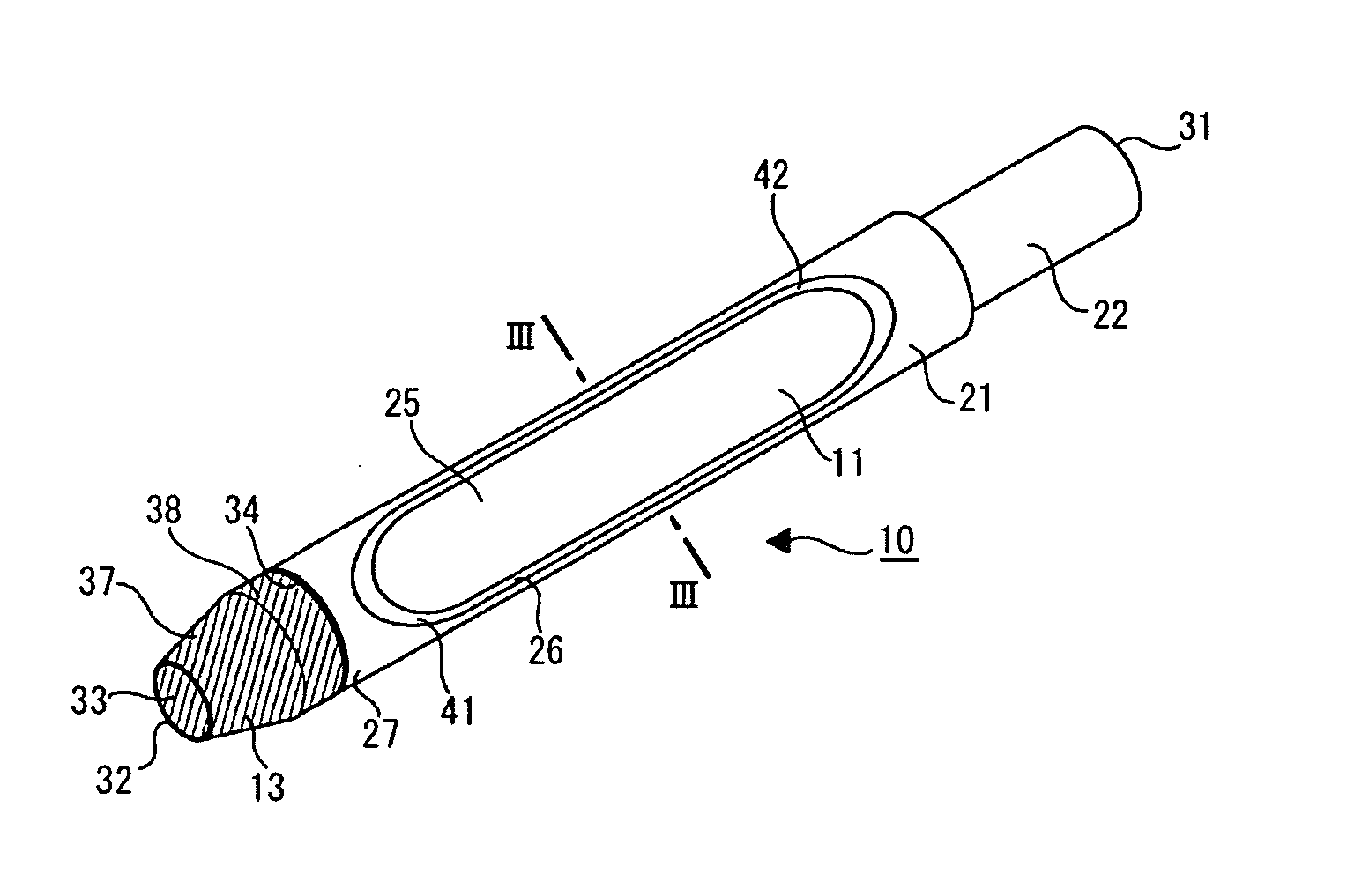
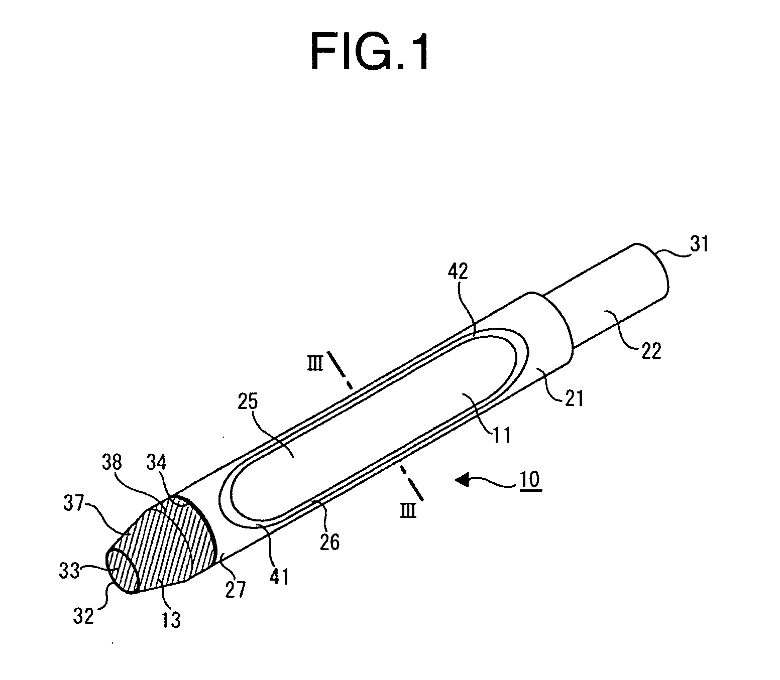
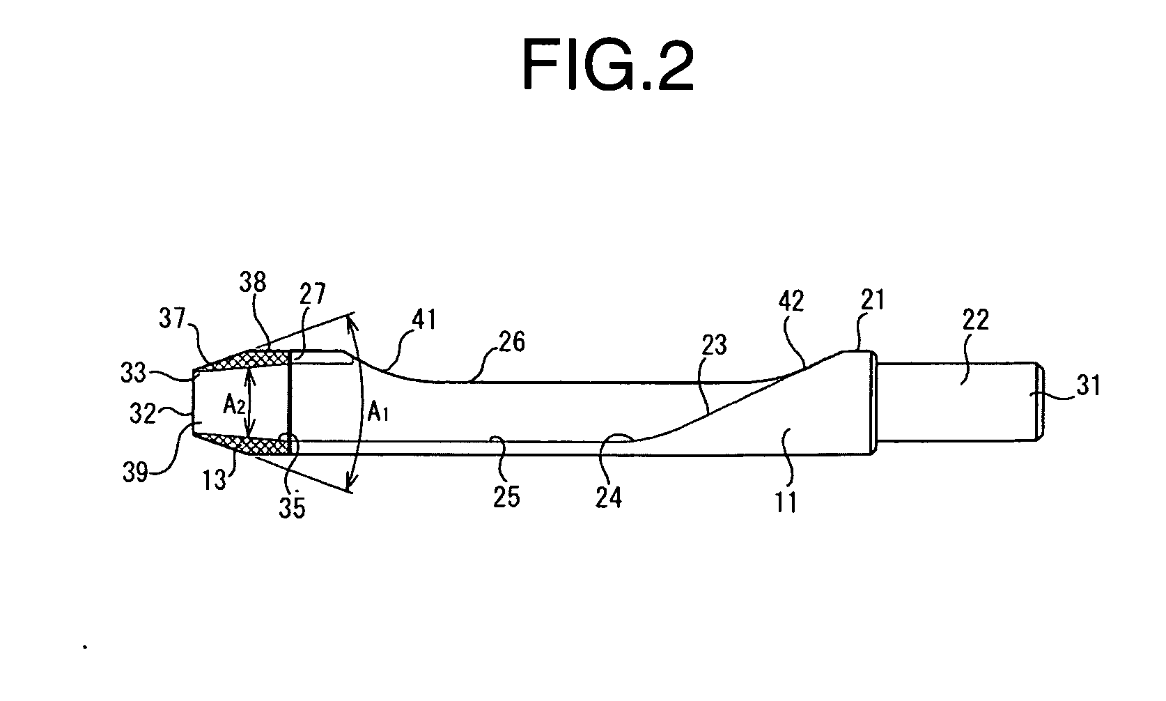
[0010] Foregoing objects are accomplished by providing an aeration tine device including: a tubular tine member extending along an axial direction thereof between a lower end portion and an upper end portion and having a lower opening bored at a center of a lower end surface, and a long side ejection opening in communication with the lower opening, the lower end surface being extending in a plane perpendicular to the axial direction; and a hard metal tip made of a hard metal material having a tapered distal end portion formed with a tip opening and a proximal end portion formed with a proximal opening bored at a center of a proximal end surface in communication with the tip opening, the proximal end surface extending in a plane perpendicular to the axial direction and coupling in an area contact with the lower end surface of the tubular tine member. Because the hard metal tip is connected to the tubular tine member in the area contact at a plane perpendicular to the axial direction, force exerted in the axial direction of the tubular tine member from the soil aerator when spiking the soil surface does not produce any divided force at the area contact region, thereby propelling the hard metal tip into the soil with full force. In addition, because the contact area between the hard metal tip and the tubular tine member is in the plane perpendicular to the axial direction, such contact surfaces can be furnished relatively easily and provide strong connection between the hard metal tip and the tubular tine member.
[0011] In accordance with the preferred embodiments, the proximal end surface preferably has an outer diameter substantially equal to an outer diameter of the lower end of the tubular tine member. Where the hard metal tip and the tubular tine member are connected as having the substantially equal outer diameter, the tine device can be smoothly pushed and pulled without resistance at the contact area between the hard metal tip and the tubular tine member. The hard metal tip may have the tip opening whose diameter is narrower than the diameter of the proximal opening. Where the diameter of the tip opening is narrower than the diameter of the proximal opening, plugs can be easily released from the interior of the hard metal tip or the tubular tine member, because the plugs tend to have a diameter smaller than that of the proximal opening.
[0012] In another aspect of the invention, an aeration tine device attached to a soil aerator, includes: a tubular tine member extending along an axial direction thereof between a lower end portion and an upper end portion and having a lower opening bored at a center of a lower end surface, and a long side ejection opening in communication with the lower opening, the lower end surface being extending in a plane perpendicular to the axial direction; a hard metal tip made of a hard metal material having a tapered distal end portion formed with a tip opening and a proximal end portion formed with a proximal opening bored at a center of a proximal end surface in communication with the tip opening, the proximal end surface extending in a plane perpendicular to the axial direction and coupling in an area contact with the lower end surface of the tubular tine member; and a metal foil insertion placed between the lower end surface of the tubular tine member and the proximal end surface of the hard metal tip for connecting the tubular tine member with the hard metal tip by brazing. The metal foil insertion operates for relaxing stresses produced due to differences between thermal coefficients of the metal hard tip and the tubular tine member.

Problems solved by technology

Although this type of aeration is beneficial, it does not bring cores to the surface, which slows the breakdown of thatch.
Repetitive insertions of the tine device into the turf bring continual wearing on the tine metal member due to friction against the turf.
The tine device described in U.S. Pat. No. 3,586,109, however, raises some problems when doing aeration to soil and turf.
Sand and soil may easily stuff up the tubelike tine having an opening at a lower end of thereof, and if stuffed up once, the tine hardly recovers from the stuffed state because the tine repeatedly spikes the surface of soil and turf and because such a repeating action makes harder the stuffed soil placed in the interior of the tine.
This friction makes uneasy the soil aeration work in use of the tine of this type and may resultantly break down the tine as to separate the hard tip from the tine body portion as a worse situation.
Fabrication of the tapered portion of the tine body portion as to render the contact area wider, however, brings higher costs, and since the tapered surface comes closely to extend parallel to the axial direction, spiking force may not be adequately transmitted to the hard tip from the tine body portion where the tapered face of the hard tip and the tapered end of the tine body portion face obliquely with respect to the axial direction of the tine.

Method used


Image

  • Aeration tine device
  • Aeration tine device
  • Aeration tine device

Examples


Embodiment Construction

[0020] Referring to FIGS. 1 to 5, an aeration tine device according to an embodiment of the invention is described. As shown in FIG. 1, the aeration tine device 10 according to the embodiment is chiefly constituted of a tubular tine member 11 in a tubular shape and a hard metal tip 13 having a frustum shape of a cone. This aeration tine device 10 is generally attached in a plural number to reciprocally moving arms of a soil aerator machine when used for turf aeration work on golf courses, soccer fields, etc.

[0021] The tubular tine member 11 is made of a carbon steel or alloy steel. The structural material for making the tubular tine member 11 can be selected from relatively hard durable materials such as carbon steels and alloy steels, but may be selected from other materials such as stainless steel, and forged steel or cast steel according to use or purpose of the tine. The tubular tine member 11 is in a substantially cylindrical shape extending longitudinally along an axial direc...


PUM


Abstract

A highly durable aeration tine device attached to a soil aerator has a tubular tine member extending cylindrically and a hard metal tip made of a hard metal material and typically made in a frustum shape of a cone, which is in an area contact with the tubular tine member between the surfaces of the tubular tine member and the hard metal tip. Each surface of the tubular tine member and the hard metal tip is extending in a plane perpendicular to the axial direction and can be fabricated easily, and the drive force provided from the soil aerator can be transmitted without loss.

Description

BACKGROUND OF THE INVENTION [0001] 1. Field of the Invention [0002] This invention relates to an aeration tine device for aerating turf and soil and, more particularly, to an aeration tine device with a side-ejecting opening suitable for aerating turf of a wide lawn surface such as golf courses. [0003] 2. Description of Related Art [0004] Turf aeration is to open channels in the soil for air and water movement and gas exchange in the root zone, and traditional turf aeration involves the process of punching holes in the soil and removing a portion of the soil and thatch layer via a coring or spooning action. To improve soil aeration, turf aeration tine devices are used for extracting plugs of turf, thatch and soil. There are two basic types of aerators: solid tine, hollow tine or core. Solid tine aeration is often called spiking and involves making a hole in the sod by pushing turf and sub-surface thatch and into the root zone. Although this type of aeration is beneficial, it does no...

Claims


Application Information

Patent Timeline
Patent Type & Authority Applications(United States)
IPC IPC(8): A01B45/02
CPCA01B45/023
Inventor UEHARA, KENJI
Owner KASHIWATOOL CORP
Learn More