Fixing structure of wire bobbin and fixing method of the same

a technology of fixing structure and wire bobbin, which is applied in the direction of threaded fasteners, manufacturing tools, electrical-based machining electrodes, etc., can solve the problems of unstable wire electrical discharge machining on the workpiece, and the wire electrode cannot be smoothly pulled out, so as to reduce the work efficiency of wire electric discharge machining and smooth pulling

Active Publication Date: 2018-09-20
FANUC LTD
View PDF0 Cites 6 Cited by
  • Summary
  • Abstract
  • Description
  • Claims
  • Application Information

AI Technical Summary

Benefits of technology

[0008]When using the speed-nut disclosed in these publications to fix the wire bobbin to the wire electrical discharge machine, the operator can fix the wire bobbin to the machine by turning the nut relative to the bolt even if the axis of the bolt and the rotational center (axis) of the wire bobbin are not aligned to each other (in a state where the axes are misaligned). As a result, the wire bobbin rotates eccentrically, so that the wire electrode cannot be smoothly pulled out from the wire bobbin and wire electrical discharge machining on the workpiece becomes unstable. Further, under such a state, there is a risk that the nut loosens as the wire bobbin rotates, so that the operator needs to interrupt the wire electric discharge machining and tighten the nut again. As a result, the work efficiency of the wire electric discharge machining decreases.

Problems solved by technology

As a result, the wire bobbin rotates eccentrically, so that the wire electrode cannot be smoothly pulled out from the wire bobbin and wire electrical discharge machining on the workpiece becomes unstable.
Further, under such a state, there is a risk that the nut loosens as the wire bobbin rotates, so that the operator needs to interrupt the wire electric discharge machining and tighten the nut again.

Method used


Image

  • Fixing structure of wire bobbin and fixing method of the same
  • Fixing structure of wire bobbin and fixing method of the same
  • Fixing structure of wire bobbin and fixing method of the same

Examples


Embodiment Construction

[0028]A fixing structure and a fixing method of a wire bobbin according to the present invention will be detailed hereinbelow by describing a preferred embodiment with reference to the accompanying drawings.

[Configuration of Wire Electrical Discharge Machine]

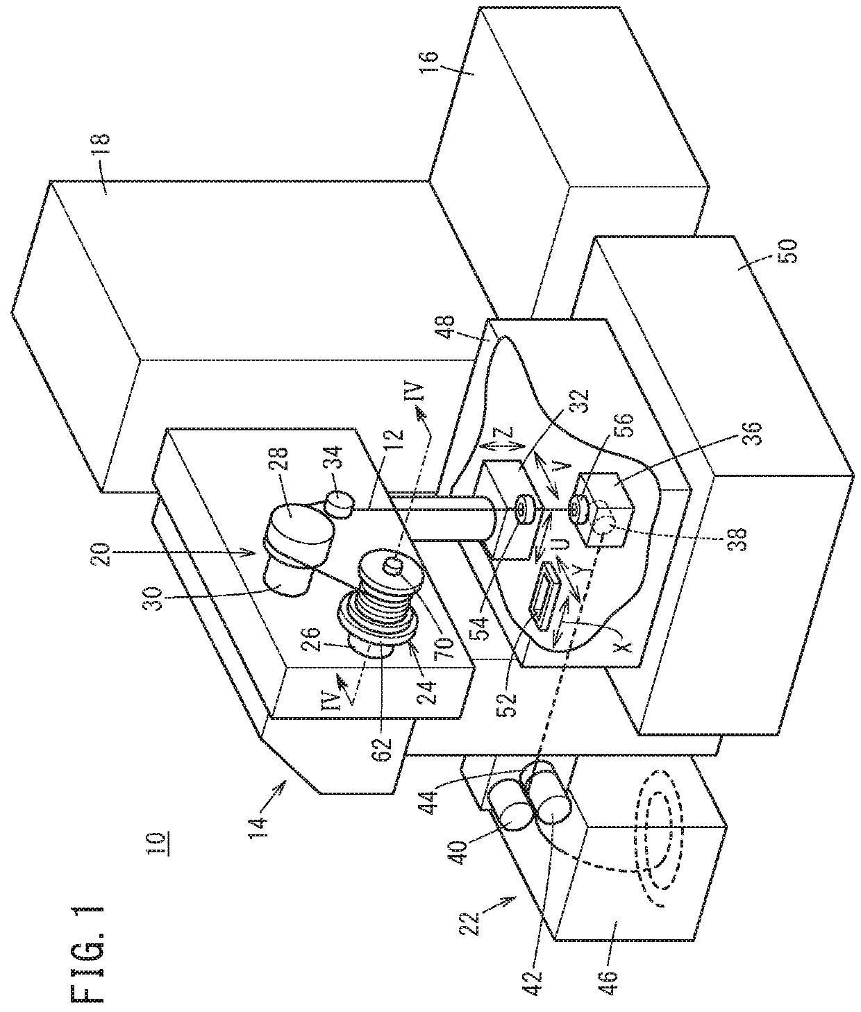
[0029]FIG. 1 is a perspective view showing an overall configuration of a wire electrical discharge machine 10. The wire electrical discharge machine 10 applies voltage across an electrode gap (clearance) formed between a wire electrode 12 and a workpiece (not shown) for electrical discharges, thereby performing electrical discharge machining on the workpiece. The wire electrode 12 is formed of, for example, tungsten-based, copper alloy-based, brass-based metal or the like. On the other hand, the material of the workpiece is, for example, a metal material such as an iron-based material or a superhard material.

[0030]The wire electrical discharge machine 10 includes a main machine body 14, a dielectric fluid unit 16 and a numerical...


PUM

PropertyMeasurementUnit
fixing structureaaaaaaaaaa
diameteraaaaaaaaaa
weightaaaaaaaaaa

Abstract

In a fixing structure and fixing method of a wire bobbin, the wire bobbin is abutted against the regulating member with the bolt inserted into the insertion hole of the wire bobbin. Then, a nut is inserted into a through hole while being kept inclined so that the axis of the through hole is substantially aligned with the axis of the bolt. Thereafter, the inclination of the nut is returned so that the axis of threaded hole becomes substantially aligned with the axis of the bolt, and then the nut is turned so as to insert part of a tapered portion into the insertion hole.

Description

CROSS-REFERENCE TO RELATED APPLICATION[0001]This application is based upon and claims the benefit of priority from Japanese Patent Application No. 2017-052133 filed on Mar. 17, 2017, the contents of which are incorporated herein by reference.BACKGROUND OF THE INVENTIONField of the Invention[0002]The present invention relates to a fixing structure and fixing method for fixing a wire bobbin to a wire electrical discharge machine.Description of the Related Art[0003]The wire electrical discharge machine shapes a workpiece in a desired contour shape by generating an electric discharge phenomenon between a wire electrode and the workpiece. Since in this process the wire electrode is consumed as the electric discharge proceeds, the new wire electrode wound on a cylindrical wire bobbin is continuously supplied toward workpiece as the wire bobbin is turned, to thereby implement wire electrical discharge machining. Therefore, it is necessary to replace the wire bobbin with a new wire electrod...

Claims


Application Information

Patent Timeline
Patent Type & Authority Applications(United States)
IPC IPC(8): B23H7/10B23H7/08
CPCB23H7/10B23H7/08B23H1/00B23H11/00B65H49/36B65H2701/36F16B37/0814
Inventor YAMAGUCHI, MEGURU
Owner FANUC LTD
Why Eureka
Try Eureka