Low-quality coal pyrolysis device

A low-quality coal pyrolysis technology, applied in special forms of dry distillation, petroleum industry, coke oven, etc., can solve complex internal heating mechanism and distribution mechanism, difficult to solve temperature control and adjustment, heating temperature uncertainty and other problems, to achieve The effect of solving major losses, continuous and reliable production operation, and improving system reliability and stability

Active Publication Date: 2015-12-09
郭秀梅
View PDF8 Cites 0 Cited by
  • Summary
  • Abstract
  • Description
  • Claims
  • Application Information

AI Technical Summary

Problems solved by technology

[0005] This kind of coal material decomposition equipment can solve the problem of decomposition of inferior coal, especially pulverized coal, but the relatively complicated internal heating mechanism and distribution mechanism are likely to cause uncertainty of heating temperature in

Method used


Image

  • Low-quality coal pyrolysis device
  • Low-quality coal pyrolysis device

Examples


Embodiment 1

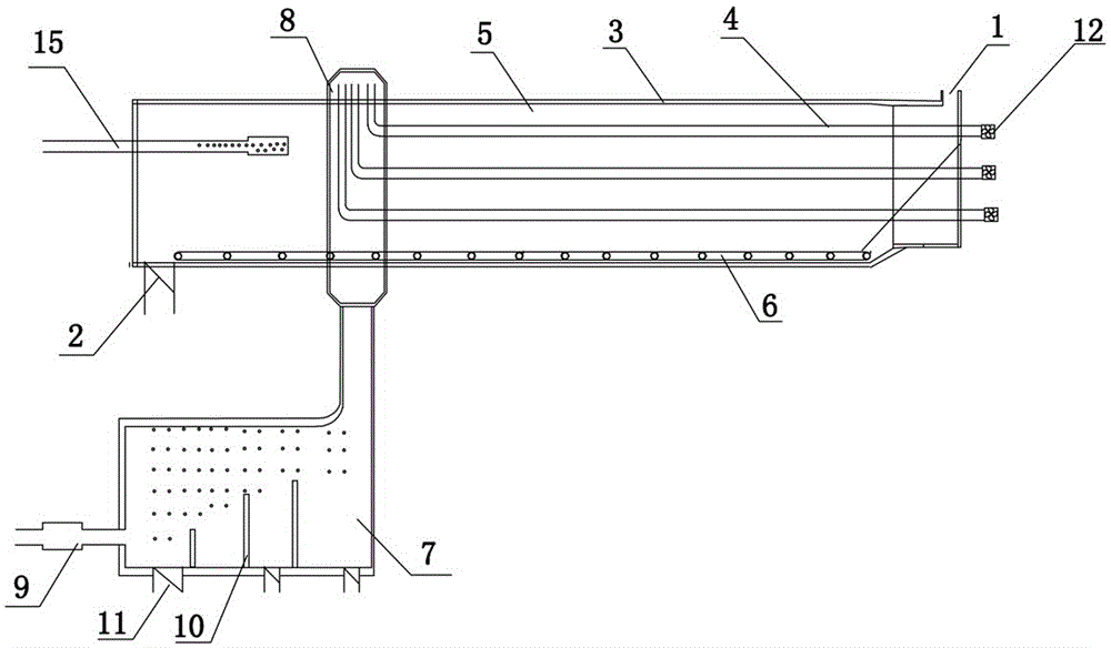
[0024] Such as figure 1 As shown, the present invention includes a closed kiln body 3 with a feed port 1 and a discharge port 2. The closed kiln body 3 is a fixed kiln body, and the fixed kiln body is provided with multiple high-temperature gas pipes 4 and multiple high-temperature gas pipes 4 Evenly arranged along the circumference of the fixed kiln body, each high-temperature gas pipe 4 protruding out of the fixed kiln body has an exhaust fan 12 at one end, and inferior coal is formed between the multiple high-temperature gas pipes 4 and the inner wall of the fixed kiln body to advance the decomposition channel 5. Inferior coal propelling and decomposing passage 5 is equipped with inferior coal propelling mechanism 6, inferior coal propelling mechanism 6 is a horizontal crawler, and the closed kiln body 3 is provided with a decomposition gas collection pipe 15 connected with inferior coal propelling and decomposing passage 5 to collect inferior coal Coal high temperature pyrol...

Embodiment 2

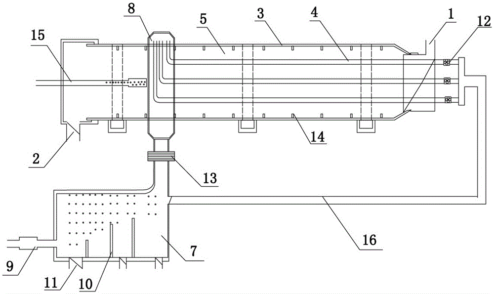
[0027] Such as figure 2 As shown, the present invention includes a closed kiln body 3 with a feed inlet 1 and a discharge port 2. The closed kiln body 3 is a rotary kiln body, and the rotary kiln body is provided with high-temperature gas pipes 4, and there are multiple high-temperature gas pipes 4 , Uniformly arranged along the circumference of the rotary kiln body, the high-temperature gas pipeline 4 extending out of the rotary kiln body is fixedly connected with an exhaust gas pipeline 16 controlled by a one-way valve, and one end of each high-temperature gas pipeline 4 protruding out of the rotary kiln body The exhaust fan 12, the low-quality coal formed between the high-temperature gas pipe 4 and the inner wall of the rotary kiln, is pushed into the decomposition channel 5. The high-temperature gas pipe 4 is provided with a heat dissipation plate 13 on the surface to increase the rate of heat dissipation, and the low-quality coal is pushed into the decomposition channel 5 ...


PUM


Abstract

The invention discloses a low-quality coal pyrolysis device. The low-quality coal pyrolysis device comprises a closed kiln body with a feed hole and a discharge hole, a high-temperature gas pipeline is arranged in the closed kiln body, a low-quality coal advancing and decomposing channel is formed between the high-temperature gas pipeline and the inner wall of the closed kiln body, and a decomposition gas collecting pipe communicated with the low-quality coal advancing and decomposing channel is arranged on the closed kiln body; the low-quality coal pyrolysis device further comprises a high-temperature gas generating device which is communicated with the high-temperature gas pipeline through a high-temperature gas distributing cover, and the high-temperature gas distributing cover is circumferentially connected with the closed kiln body in a sealing mode. According to the low-quality pyrolysis device, the high-temperature gas generating device is arranged and connected with the high-temperature gas pipeline through the high-temperature gas distributing cover, so that the reliability and stability of the low-quality coal pyrolysis device are improved fundamentally.

Description

Technical field [0001] The invention relates to the technical field of comprehensive utilization of coal materials, energy saving and emission reduction, and in particular to a low-quality coal pyrolysis device. Background technique [0002] In my country, the reserves of low-quality coal represented by lignite and low-grade bituminous coal account for more than 55% of the total coal resources, mainly distributed in eastern Inner Mongolia, Yunnan, Xinjiang and the Ordos Basin. With the increasing use of high-quality coals, the optimal utilization of low-quality coals becomes increasingly important. Compared with the technical or economic problems in the direct utilization of inferior coal, the hierarchical utilization of inferior coal after upgrading should become an important direction. As a technology that is later than the industrialization of coal gasification technology, the upgrading of inferior coal is invisibly given the expectation of "misplaced coal use with coal gasif...

Claims


Application Information

Patent Timeline
IPC IPC(8): C10B53/04
Inventor 郭秀梅
Owner 郭秀梅
Why Eureka
Try Eureka