Method for preventing landslides induced by inappropriate liquid injection intensity in in-situ leaching mining

An in-situ leaching and landslide technology, which is applied in the direction of improving process efficiency, can solve the problems of non-ionic rare earth extraction and landslides, and achieve the effect of avoiding waste and increasing the bonding strength

Active Publication Date: 2015-12-09
四川共拓岩土科技股份有限公司 +1
3 Cites 2 Cited by

AI-Extracted Technical Summary

Problems solved by technology

[0005] However, if the contact portion between the clay layer and the ore body layer, or the contact portion between the ore body layer and the bedrock, slips when the injection intensity (that is...

Abstract

The invention discloses a method for preventing landslides induced by inappropriate liquid injection intensity in in-situ leaching mining. The method comprises the following steps: S1, drilling a liquid injection hole; S2, integrating an upper-layer mold bag (1), a lower-layer mold bag (2) and other parts into a whole; S3, injecting cement slurry from an inlet of a slurry injection pipe I, wherein the cement slurry enters the upper-layer mold bag (1), so that the slurry injection of the upper-layer mold bag (1) is realized; injecting cement slurry from an inlet of a slurry injection pipe II (6), wherein the cement slurry enters the lower-layer mold bag (2), so that the slurry injection of the lower-layer mold bag (2) is realized; S4, enabling a medicament to be inlet into a liquid injection pipe (4) from an inlet end of the liquid injection pipe (4), wherein the medicament enters a region formed by the upper-layer mold bag (1), the liquid injection hole (10) and the lower-layer mold bag (2), so that the injection of the medicament is realized. The method disclosed by the invention has the benefits that the medicament can be prevented from entering a non-ore body layer and a space between the non-ore body layer and an ore body layer, and due to the effect of an anchor rod, a slippage phenomenon generated between a clay layer and the ore body layer, as well as between the ore body layer and a bed rock is effectively avoided.

Application Domain

Process efficiency improvement

Technology Topic

In situ leachCement slurry +4

Image

  • Method for preventing landslides induced by inappropriate liquid injection intensity in in-situ leaching mining

Examples

  • Experimental program(1)

Example Embodiment

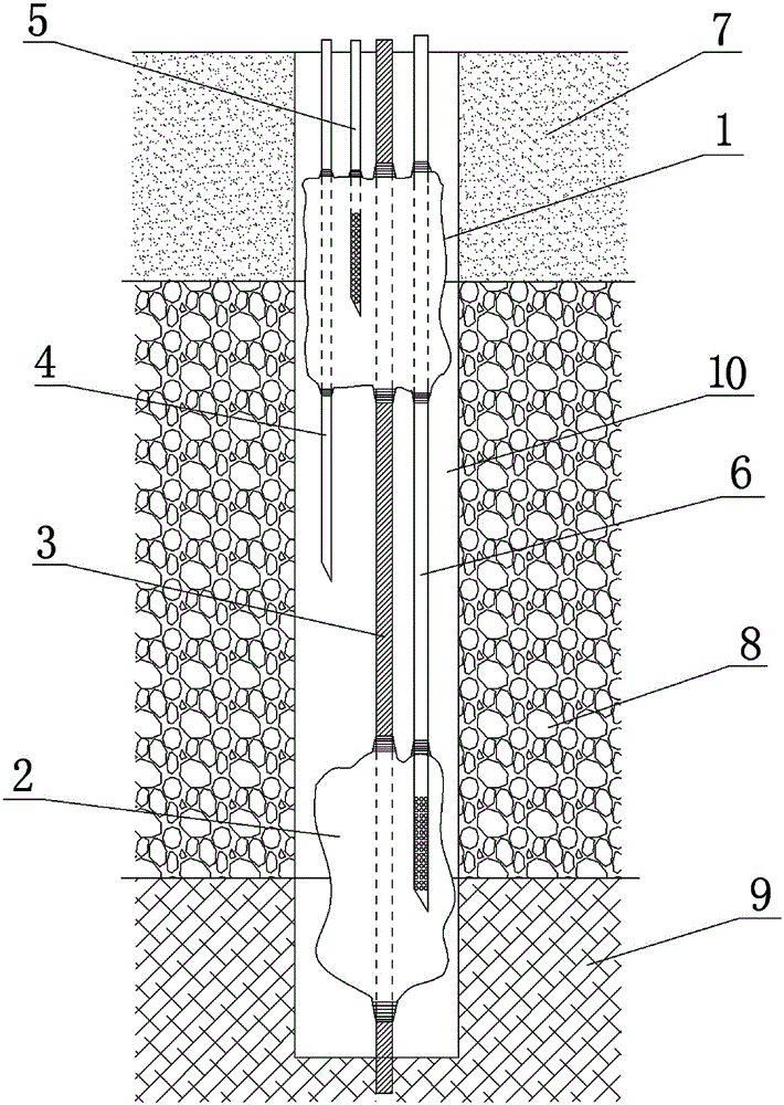
[0015] The present invention will be further described below in conjunction with the accompanying drawings. The protection scope of the present invention is not limited to the following:
[0016] Such as figure 1 As shown, a method for preventing landslides caused by improper liquid injection intensity in in-situ leaching mining uses a liquid injection device to inject the medicament for extracting ionic rare earths into the ore body. The liquid injection device consists of the upper layer The mold bag 1, the lower mold bag 2, the anchor rod 3, the liquid injection pipe 4, the grouting pipe I5 and the grouting pipe II6 are composed. The upper mold bag 1 is sleeved at the upper end of the anchor rod 3, and the lower mold bag 2 is sleeved At the lower end of the anchor rod 3, the grouting pipe I5 is inserted into the upper mold bag 1 from the top of the upper mold bag 1, and the cylindrical surface of the grouting pipe I5 is provided with a plurality of grouting holes communicating with the inner cavity of the upper mold bag 1 The said grouting pipe II6 penetrates the upper mold bag 1 from the top of the upper mold bag 1 and is inserted into the lower mold bag 2. The cylindrical surface of the grouting pipe II6 is provided with a plurality of grouting communicating with the inner cavity of the lower mold bag 2 The liquid injection pipe 4 is set through the upper mold bag 1 from the top of the upper mold bag 1, and the liquid outlet of the liquid injection pipe 4 is set between the upper mold bag 1 and the lower mold bag 2. The prevention is in the original The method for inducing landslides due to improper liquid injection intensity in in-situ leaching mining includes the following steps:
[0017] S1. Drill a liquid injection hole, use a drill to drill down from the top of the clay layer 7 through the clay layer 7 and the ore body layer 8, and drill into the bedrock 9 to a depth of 2~2.4m to form the liquid injection hole 10;
[0018] S2. Assemble the upper mold bag 1 and the lower mold bag 2 with the anchor rod 3, the injection pipe 4, the grouting pipe I5 and the grouting pipe II6 with metal wires. The gap between the upper mold bag 1 and the lower mold bag 2 The distance is determined according to the thickness of the ore body layer 8, to ensure that the bolt 3 is inserted into the bottom of the injection hole 10, and to ensure that the boundary line between the clay layer 7 and the ore body layer 8 is perpendicular to the upper and lower ends of the upper mold bag 1. The distances are greater than or equal to 50cm, while ensuring that the vertical distance between the boundary line between the ore body layer 8 and the bedrock 9 and the upper and lower ends of the lower mold bag 2 is greater than or equal to 50cm;
[0019] S3. Inject the cement slurry, inject the cement slurry through the inlet of the grouting pipe I, the cement slurry enters the upper mold bag 1 through the grouting hole on the grouting pipe I, and the injected cement slurry gradually increases the volume of the upper mold bag 1 , The upper mold bag 1 is tightly attached to the boundary between the clay layer 7 and the ore body layer 8 under the action of cement diffusion, which increases the bonding strength between the clay layer 7 and the ore body layer 8. Under the action of 3, the phenomenon of slippage and landslide between the clay layer 7 and the ore body layer 8 is avoided, so as to realize the grouting of the upper mold bag 1. At the same time, the cement slurry is injected through the inlet of the grouting pipe II6. The grouting hole on the grouting pipe II6 enters the lower mold bag 2, and the injected cement slurry gradually increases the volume of the lower mold bag 2. The lower mold bag 2 is tightly attached to the ore body layer 8 under the action of cement diffusion. At the boundary line between the ore body layer 8 and the bed rock 9, the bonding strength between the ore body layer 8 and the bed rock 9 is increased. Under the action of the bolt 3, the slip and the slip between the ore body layer 8 and the bed rock 9 are avoided. The phenomenon of landslide, so as to realize the grouting of the lower mould bag 2;
[0020] S4. The injection of the medicament, the injection pipe 4 is passed through the inlet end of the injection pipe 4, and the medicament enters the area formed by the upper mold bag 1, the injection hole 10 and the lower mold bag 2, thereby realizing the injection of the medicament. Dissolve the ionic rare earth in the ore body into the medicament to become the mother liquor, and realize the collection of the mother liquor. This method effectively avoids the problem of the clay layer 7 and the ore body layer 8 when the medicament injection speed is too fast or the injection amount is too large. The phenomenon of slippage at the boundary, the boundary between the ore body layer 8 and the bedrock 9 causes landslides, and at the same time, it prevents the agent from entering the non-ore body layer and between the ore body layer and the non-ore body layer. Waste of medicine.

PUM

no PUM

Description & Claims & Application Information

We can also present the details of the Description, Claims and Application information to help users get a comprehensive understanding of the technical details of the patent, such as background art, summary of invention, brief description of drawings, description of embodiments, and other original content. On the other hand, users can also determine the specific scope of protection of the technology through the list of claims; as well as understand the changes in the life cycle of the technology with the presentation of the patent timeline. Login to view more.

Similar technology patents

Hard alloy coating matrix added with rare earth

InactiveCN102644001APrevent rare earth oxidationHigh bonding strength
Owner:CHENGDU BANGPU CUTTING TOOLS CO LTD

Speaker and method of producing the same

InactiveCN101053278AHigh bonding strengthachieve flat
Owner:PANASONIC CORP

Surface plating technique for polymer material product

ActiveCN105316624AImprove flatness and finishHigh bonding strength
Owner:无锡纳弧新材料科技有限公司

Lead and carbon mixture and method for manufacturing lead-acid battery electrode plate

ActiveCN103078083AHigh bonding strengthFlexible process
Owner:湖北雄韬电源科技有限公司

Classification and recommendation of technical efficacy words

  • High bonding strength
  • avoid wasting

Marine fender

InactiveUS6050211Ahigh bonding strengthhigh slip property
Owner:BRIDGESTONE CORP

Method for preparing ceramic particle enhanced steel-base composite material cast by evaporative pattern casting die

InactiveCN102489686AHigh bonding strengthImproved dimensional accuracy and surface quality
Owner:KUNMING UNIV OF SCI & TECH

A wireless channel allocation method based on cells along the train

InactiveCN102300319Aavoid wastingSolving resource constraints
Owner:BEIJING JIAOTONG UNIV

Method and system for automatically controlling flow of peer-to-peer networking service

InactiveCN101577671Aavoid wastingGood implementation flexibility and applicability
Owner:BEIJING VENUS INFORMATION TECH

Data processing method, device and system

InactiveCN103294702Aavoid redundancyavoid wasting
Owner:上海淼云文化传播有限公司

System and method for intelligent reservation of district temporary parking stalls

InactiveCN107545769AOptimize parking time and space layoutavoid wasting
Owner:WUHAN SHENJIE TECH CORP LTD
Why Eureka
Try Eureka