
Spinning unhairing machine

A wool machine and dehairing technology, applied in the field of textile machinery, can solve the problems of incomplete dehairing, imperfect structure setting, poor dehairing effect, etc., and achieve the effect of ensuring efficiency

Inactive Publication Date: 2015-12-09
HAIAN LIANFA ZHANGSHI YARN DYED
View PDF1 Cites 2 Cited by
  • Summary
  • Abstract
  • Description
  • Claims
  • Application Information

AI Technical Summary

Problems solved by technology

The above invention only removes hair on one side of the fabric, and the structure is not perfect; at the same time, the hair is removed through the air outlet device and the air suction device, the hair removal is incomplete, and the hair removal effect is poor

Method used

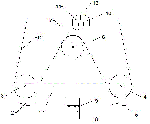

Image

  • Spinning unhairing machine

Examples


Embodiment Construction

[0014] Such as figure 1 As shown, the present invention discloses a textile dehairing machine, which includes a pair of T-shaped supports 1, a roller arranged between the pair of T-shaped supports 1, a depilatory device and an air suction device.

[0015] A pair of T-shaped brackets 1 are arranged in parallel, the first roller 3 and the second roller 4 are respectively arranged at the two ends of the horizontal direction, and the third roller 6 is arranged at the vertical top; The arc-shaped hair-removing brush A2 and the arc-shaped hair-removing brush B5 at the bottom of the roller 4, the arc-shaped hair-removing brush C7 arranged on the top of the third roller 6; the suction device includes a suction fan A8 and a suction fan B13, and a suction fan A8 It is arranged at the bottom of a pair of T-shaped brackets 1, and a filter screen 9 is arranged inside the suction fan A8; the suction fan B13 is N-shaped, and is arranged on the upper end of the arc-shaped hair removal brush C...


PUM


Abstract

The invention relates to a spinning unhairing machine. The spinning unhairing machine comprises a pair of T-shaped supports, rollers which are arranged between the pair of supports, unhairing devices and an air draught device, wherein the pair of T-shaped supports are arranged in parallel; a first roller and a second roller are respectively arranged at the horizontal ends; a third roller is arranged at the vertical top end; the unhairing device comprises an arc unhairing brush A and an arc unhairing brush B which are arranged at the bottom end of the first roller and the bottom end of the second roller, and an arc unhairing brush C which is arranged at the top end of the third roller; the air draught device comprises a suction fan A and a suction fan B; the suction fan A is arranged at the bottom of the T-shaped support; a filter screen is arranged in the suction fan A; and the suction fan B is arranged on the upper end of the arc unhairing brush C. The spinning unhairing machine has the advantages that the spinning unhairing machine puts fabrics between the rollers and the arc unhairing brushes; the arc unhairing brushes can perform unhairing processing of two sides of the fabrics and unhair the fabrics completely; and at the same time the air draught device can suck the removed hairs, thus preventing pollution.

Description

technical field [0001] The invention relates to a textile hair removal machine, which belongs to the technical field of textile machinery. Background technique [0002] For many textiles, textiles are prone to pilling because of friction with external objects. After a long time, the fibers of the textile will slip and loosen due to friction, and the top of the fiber will be pulled out of the surface of the fabric, thus causing the fabric to fluff. Afterwards, as the friction continues, the fluff fibers continue to gather together to form a ball, so the hair must be removed before the fibers pill. [0003] The invention patent with the patent number of 201320768659.2 mentions a textile dehairing device, which includes a cloth releasing roller and a cloth receiving roller. The first roller and the second roller are set, the line of the cloth releasing roller and the cloth receiving roller is perpendicular to the line of the first roller and the second roller, and the first ro...

Claims


Application Information

Patent Timeline
IPC IPC(8): D06G1/00
Inventor 孙刚张宏德
Owner HAIAN LIANFA ZHANGSHI YARN DYED
Learn More