Oil well liquid level measuring method and device

A technology of liquid level measurement and measurement method, which can be used in construction and other directions, can solve problems such as measurement errors, and achieve the effect of improving measurement accuracy

Inactive Publication Date: 2015-12-09
CHINA PETROLEUM & CHEM CORP +1
View PDF5 Cites 3 Cited by
  • Summary
  • Abstract
  • Description
  • Claims
  • Application Information

AI Technical Summary

Problems solved by technology

[0004] In practical application, the echolocation method is easily affected by the foam section in the oil well, resulting in measurement errors

Method used


Image

  • Oil well liquid level measuring method and device
  • Oil well liquid level measuring method and device
  • Oil well liquid level measuring method and device

Examples


Embodiment Construction

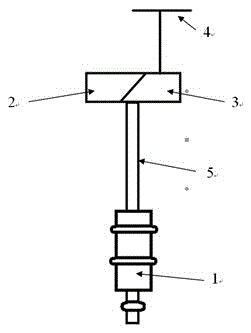
[0018] see figure 1 , The measurement method of the present invention uses the following device: the power supply 4 is connected with the submersible screw pump 1 by the cable 5 through the torque tester 2 and the frequency converter 3 . Wherein, the torque tester 2 and the frequency converter 3 can be combined together in the electrical equipment. The submersible screw pump 1 is installed underground in the oil well.

[0019] A method for measuring oil well liquid level of the present invention is obtained by calculation, and its steps are as follows,

[0020] a. Ground inverter 3 output frequency f 1 , calculate the speed n of the submersible screw pump 1, and substitute n into the formula (j), and calculate the torque T of the submersible screw pump 1 3 (f 1 );

[0021] T 3 =91.3δ 0 -n 0.45 +46.5(j)

[0022] In the formula, δ 0 is a constant

[0023] b. The ground torque tester 2 measures the total power output torque T 1 (f 1 );

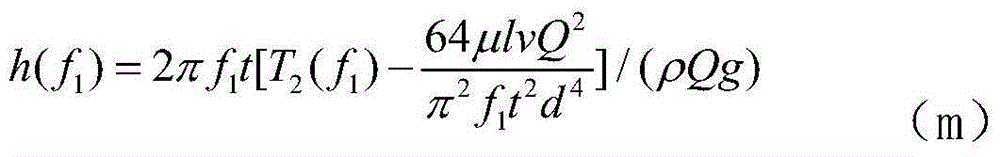
[0024] c. Calculate the torq...


PUM


Abstract

The invention relates to an oil well liquid level measuring method and device for oil well liquid level measurement. The method includes the following steps that a, a ground frequency converter outputs frequency f1, the rotation speed n of a submersible screw pump is obtained through calculation, n is substituted into the formula of T3=91.3delta0-n0.45+46.5, and the torque T3(f1) of the submersible screw pump is obtained through calculation; b, the total power supply output torque T1(f1) is measured through a ground torque tester; c, the torque T2(f1) of lifting liquid is calculated through the formula of T2(f1)=T1(f1)-T3(f1); d, the height h(f1) of the lifting liquid is calculated through the formula in the specification. According to the measuring device, a power supply is connected with the submersible screw pump through a cable by means of the torque tester and the frequency converter. The measurement method and device do not depend on echo location and improve measurement precision.

Description

technical field [0001] The invention relates to a method and a device for measuring the fluid level of an oil well downhole in oil exploitation, in particular to a method for measuring the liquid level of an oil well and a device for measuring the liquid level. Background technique [0002] The basic principle of the current oil well liquid level measuring device is the echolocation of the sonar system: after the sound wave is emitted by the transmitter, it reaches the detection target through the propagation medium, and then the sound wave is reflected by the target and returns to the emission point, and is received by the receiving transducer , The transducer converts sound energy into electrical signals through electrical and acoustic conversion. The electrical signal is amplified, filtered and processed, and the final processing result is fed to the display system. In the above process, the round-trip time of the acoustic wave signal can be obtained through processing. ...

Claims


Application Information

Patent Timeline
Patent Type & Authority Applications(China)
IPC IPC(8): E21B47/047
Inventor 朱玉波熊敏高志鹏李洪泉段其敬
Owner CHINA PETROLEUM & CHEM CORP
Why Eureka
Try Eureka