Method and device for controlling light spots of heat collector
A heat collector and light spot technology is applied in the field of heat collection towers to reduce costs, reduce installation and debugging workload, and improve stability.
- Summary
- Abstract
- Description
- Claims
- Application Information
AI Technical Summary
Problems solved by technology
Method used
Image
Examples
Embodiment 1
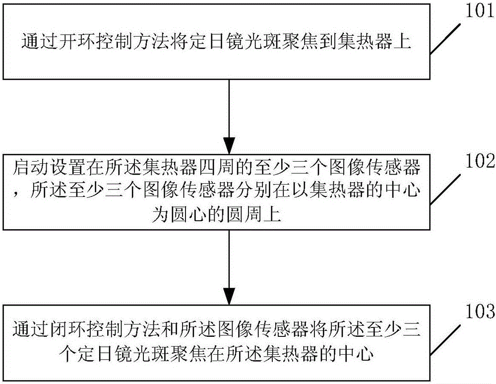
[0058] refer to figure 1 , figure 1 It is a schematic flowchart of the first embodiment of the method for controlling the light spot of the heat collector according to the embodiment of the present invention.
[0059] In Embodiment 1, the method for controlling the light spot of the heat collector includes:
[0060] Step 101, focusing the heliostat spot on the heat collector through an open-loop control method;
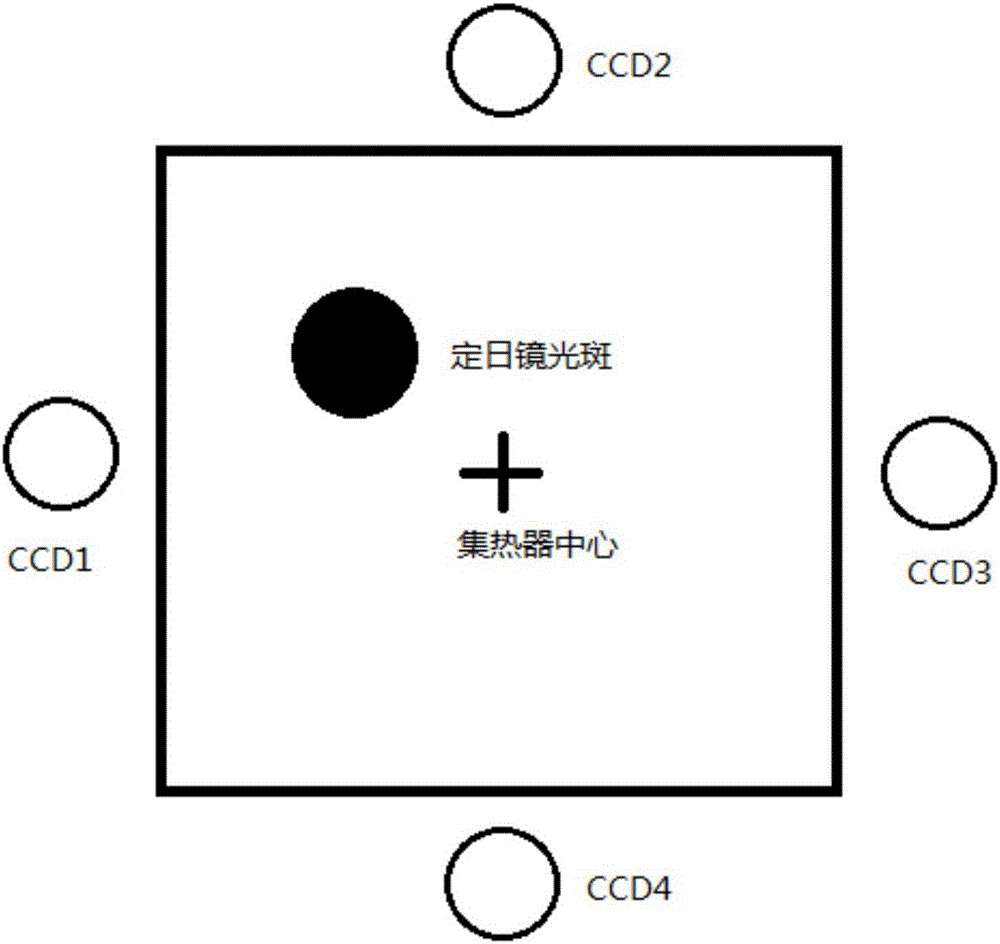
[0061] Step 102, start at least three image sensors arranged around the heat collector, and the at least three image sensors are respectively on the circle centered on the center of the heat collector;
[0062] Preferably, the activation of at least three image sensors arranged around the heat collector includes:
[0063] Start the upper and lower image sensors arranged around the heat collector symmetrically with the heat collector as the center; or,
[0064] Start two left and right image sensors arranged around the heat collector symmetrically with the heat col...
Embodiment 2
[0082] refer to Figure 4 , Figure 4 It is a schematic flowchart of the second embodiment of the method for controlling the light spot of the heat collector according to the embodiment of the present invention.
[0083] On the basis of Embodiment 1, focusing the heliostat spot before the center of the heat collector through the closed-loop control method and the at least three image sensors further includes:
[0084] Step 104, making the light spot of the image sensor in an unsaturated state through the filter device arranged in front of the image sensor;
[0085] Step 105 , calibrating the grayscale values of the image sensors, so that the grayscale values of the symmetrical image sensors are the same under the same lighting conditions.
Embodiment 3
[0087] refer to Figure 5 , Figure 5 It is a schematic diagram of the functional modules of the device for controlling the light spot of the heat collector according to the embodiment of the present invention.
[0088] In the third embodiment, the device for controlling the light spot of the heat collector includes:
[0089] The first focusing module 501 is used to focus the heliostat spot on the heat collector through an open-loop control method;
[0090] A starting module 502, configured to start at least three image sensors arranged around the heat collector;
[0091] Preferably, refer to Image 6 , Image 6 It is a schematic diagram of the functional modules of the startup module 502 in the embodiment of the present invention. The startup module 502 includes:
[0092] The first starting unit 601 is used to start the upper and lower image sensors arranged around the heat collector symmetrically with the heat collector as the center;
[0093] The second starting unit...
PUM
 Abstract
Description
Claims
Application Information
 - R&D Engineer
- R&D Manager
- IP Professional
- Industry Leading Data Capabilities
- Powerful AI technology
- Patent DNA Extraction
Browse by: Latest US Patents, China's latest patents, Technical Efficacy Thesaurus, Application Domain, Technology Topic, Popular Technical Reports.
© 2024 PatSnap. All rights reserved.Legal|Privacy policy|Modern Slavery Act Transparency Statement|Sitemap|About US| Contact US: help@patsnap.com


