Meteorologic correction model in slope deformation monitoring

A technology for calibrating models and meteorology, applied in measuring devices, instruments, using wave/particle radiation, etc., can solve problems such as complex data processing and large data volume

Active Publication Date: 2015-12-09
KUNMING UNIV OF SCI & TECH
View PDF3 Cites 9 Cited by
  • Summary
  • Abstract
  • Description
  • Claims
  • Application Information

AI Technical Summary

Problems solved by technology

[0005] ①PS technology can solve the problem of space-time decorrelation and atmospheric effect at the same time, but requires a large amount of data and complex data processing, and is only suitable for small-scale areas with smooth spatial chang

Method used


Image

  • Meteorologic correction model in slope deformation monitoring
  • Meteorologic correction model in slope deformation monitoring
  • Meteorologic correction model in slope deformation monitoring

Examples


Embodiment 1

[0057] According to the actual situation of the Nuozhadu Hydropower Station, a total of 10 angular reflectors were installed on the slope after field investigation, and they were evenly distributed on the slope; In the shed, the monitoring frequency is 24-hour real-time monitoring, and the one-time sampling time is 6 minutes; at the same time, precision instruments are used to monitor the temperature, pressure and humidity meteorological parameters, and the schematic diagram of the invented data acquisition device is as follows Figure 6 As shown, the present embodiment adopts the real-time monitoring data from 4:30 to 6:00 pm on August 14, 2014, from 3:30 to 5:00 pm on August 20, and from 4:00 pm to 6:00 pm on August 27, 2014.

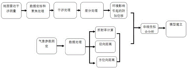
[0058] Such as figure 1 As shown, the meteorological correction model in slope deformation monitoring, its steps include the following:

[0059] Step 1. First, according to the temperature, relative humidity and air pressure monitored in real time, ...

Embodiment 2

[0081] The meteorological correction model in slope deformation monitoring, its steps include the following:

[0082] Step 1. First, according to the temperature, relative humidity and air pressure monitored in real time, the refractive index change value is calculated by using the microwave refractive index calculation formula of the Eisen-Froom empirical formula recommended by the International Union of Geodesy and Geophysics;

[0083] Step 2. Perform calibration, focusing, interference and differential processing on the radar monitoring data, and combine the geometric position of the corner reflector, estimated signal-to-noise ratio, thermal signal-to-noise ratio and correlation information to obtain the influence of the weather on the corner reflector points at different times The additional displacement caused by;

[0084] Step 3. According to the calculated refractive index change value obtained in step 1, the azimuth coordinate value and the distance coordinate value of...


PUM


Abstract

The invention relates to a meteorologic correction model in slope deformation monitoring, wherein the meteorologic correction model belongs to the technical field of ground radar monitoring. Firstly according to a temperature, a relative humidity and an air pressure which are monitored in real time, a refractive index change value is calculate through an Essen Froome empirical formula which is recommended by International Union of Geodesy and Geophysics. Scaling, focusing, interference and difference processing are performed on radar monitoring data. An additional displacement of an angle reflector caused by a meteorologic effect is obtained according to the geometric position, an estimated signal-to-noise ratio, a thermal signal-to-noise ratio and correlation information of the angle reflector. According to the calculated refractive index change value, the azimuth coordinate value and the range coordinate value of the angle reflector, the meteorologic correction model of the ground radar in slope deformation monitoring is established by means of a nonlinear fitting method, so that a difference between the calculated value of the model and the additional displacement which is caused by an environment effect is minimized. The meteorologic correction model can effectively correct the meteorologic effect.

Description

technical field [0001] The invention relates to a meteorological correction model in slope deformation monitoring, which belongs to the technical field of ground radar monitoring. Background technique [0002] Compared with deformation monitoring methods such as GPS measurement based on single-point measurement, ground radar interferometry technology has the advantages of long-distance, large-scale, continuous space coverage, real-time, non-contact and high security. , land subsidence, landslides, and glacier displacement and other deformation monitoring fields have been widely used. Ground synthetic aperture radar interferometry technology uses step-frequency continuous high-frequency microwaves as propagation signals. Microwave signals propagate in the air and are affected by environmental factors such as humidity, temperature, and air pressure. Refraction is the main source of error in radar interferometry and has become a constraint for radar interferometry. The main fa...

Claims


Application Information

Patent Timeline
IPC IPC(8): G01B15/06
Inventor 左小清余红楚
Owner KUNMING UNIV OF SCI & TECH
Why Eureka
Try Eureka