Method for calculating work load based on beam surface strain values measured by optical fiber sensors

A fiber optic sensor and workload technology, which is applied in the field of fiber optic sensing, can solve the problems of time-consuming, labor-intensive, and high-cost sensors, and achieve the effects of reducing complexity, light weight, and high computing efficiency

Active Publication Date: 2015-12-09
山东双测安全信息技术产业研究院有限公司
View PDF3 Cites 18 Cited by
  • Summary
  • Abstract
  • Description
  • Claims
  • Application Information

AI Technical Summary

Problems solved by technology

Among them, this method is time-consuming and labor-intensive to install the sensor, and the cost is high

Method used


Image

  • Method for calculating work load based on beam surface strain values measured by optical fiber sensors
  • Method for calculating work load based on beam surface strain values measured by optical fiber sensors
  • Method for calculating work load based on beam surface strain values measured by optical fiber sensors

Examples


Embodiment Construction

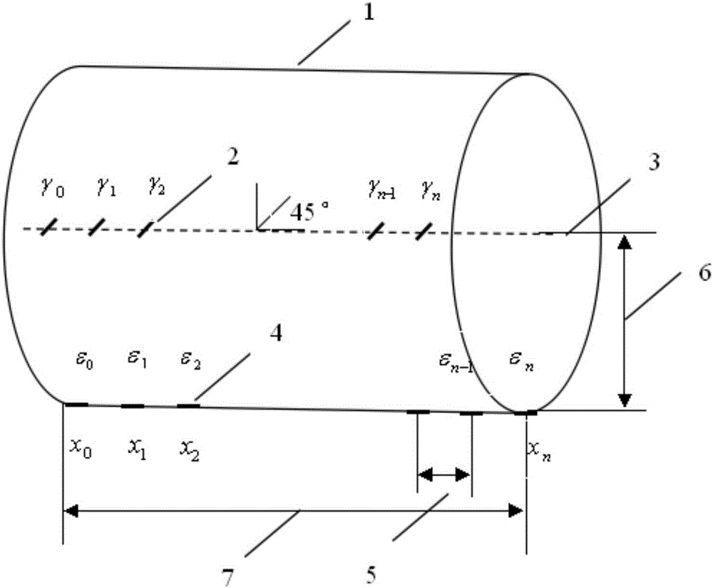
[0024] The implementation object is as figure 1 The cantilever beam structure shown is fixed at the left end and the free end of the beam at the right end. figure 1 Middle, 1-beam; 2-FBG sensor (to measure torsional strain); 3-axis of beam; 4-FBG sensor (to measure bending strain); 5-sensor interval △l; 6-c (sensor to neutral axis or center The distance of the surface); 7-the length l of the beam. The bending strain optical fiber sensor is mounted along the axial direction of the beam, and the torsional strain optical fiber sensor is mounted along the axial direction of the beam at an angle of 45° to the axial direction.

[0025] The present invention is specifically realized as follows:

[0026] (1) Install multiple optical fiber sensors on the beam structure. When measuring the bending load, stick it along the axial direction of the beam; when measuring the torsional load, the optical fiber sensor should be at 45° to the axis of the beam;

[0027] (2) After the fiber opti...


PUM


Abstract

The invention discloses a method for calculating a work load based on beam surface strain values measured by optical fiber sensors, and aims to utilizing an optical fiber Bragg grating (FBG) technology to measure the beam surface internal strain values and then obtain real-time planar applied bending or torsion work load data. According to the invention, FBG strain sensors are utilized and are pasted on a beam structure at certain intervals, so that the beam is divided into a plurality of regions. By adopting the method, the torque, the bending moment and the shearing force of the cross section where the optical fiber sensor is arranged are calculated, and then the work load value of the region is calculated by utilizing the shearing forces of two adjacent cross sections. Specific embodiment schemes are provided by invention for verifying the precision of the method. Compared with other methods for measuring the work load of the beam in the prior art, the method provided by the invention is interference resistant, time-saving, cost-saving and high in efficiency.

Description

technical field [0001] The invention relates to a method for calculating a working load based on beam surface strain values ​​measured by an optical fiber sensor, and belongs to the technical field of optical fiber sensing. Background technique [0002] Currently, the industry employs a rigorous but time-consuming design approach that relies heavily on computational methods, such as finite element modeling (FEM), to obtain the operating loads on beam structures. But finite element modeling is a method that consumes a lot of manpower and economic cost. [0003] Further, for real-time loads associated with aircraft wings, the method used is a relatively extensive "strain gauge / load calibration" method developed in the 1950s. First, a series of discrete traditional strain gauges are installed inside the wing structure, and a series of concentrated loads are applied to the wing surface to calibrate the response of the strain gauges under these loads, which is called the influen...

Claims


Application Information

Patent Timeline
Patent Type & Authority Applications(China)
IPC IPC(8): G01L1/24G01B11/16
Inventor 魏鹏郑雷雷
Owner 山东双测安全信息技术产业研究院有限公司
Why Eureka
Try Eureka