Optimal antenna directional diagram selection radar angular super-resolution method

An antenna pattern and optimal antenna technology, applied in the field of scanning radar angle super-resolution imaging, can solve problems such as missing and high-frequency component reduction

Active Publication Date: 2015-12-09
UNIV OF ELECTRONICS SCI & TECH OF CHINA
View PDF3 Cites 14 Cited by
  • Summary
  • Abstract
  • Description
  • Claims
  • Application Information

AI Technical Summary

Problems solved by technology

The out-of-focus image can be regarded as the result of convolution between the object and the point spread function, which often leads to the reduction or absence of high-frequency components in the image

Method used


Image

  • Optimal antenna directional diagram selection radar angular super-resolution method
  • Optimal antenna directional diagram selection radar angular super-resolution method
  • Optimal antenna directional diagram selection radar angular super-resolution method

Examples


Embodiment Construction

[0090] The present invention will be further elaborated below in conjunction with the accompanying drawings and specific embodiments.

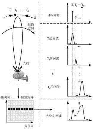
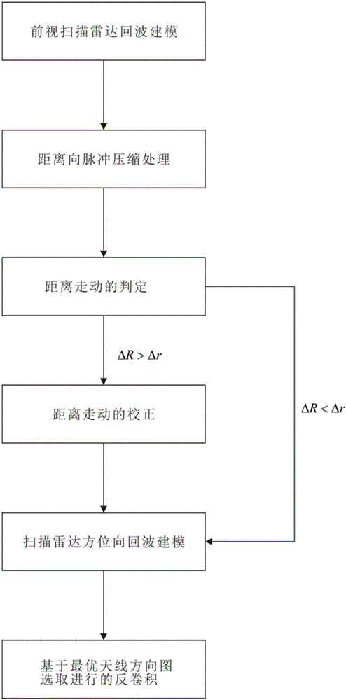
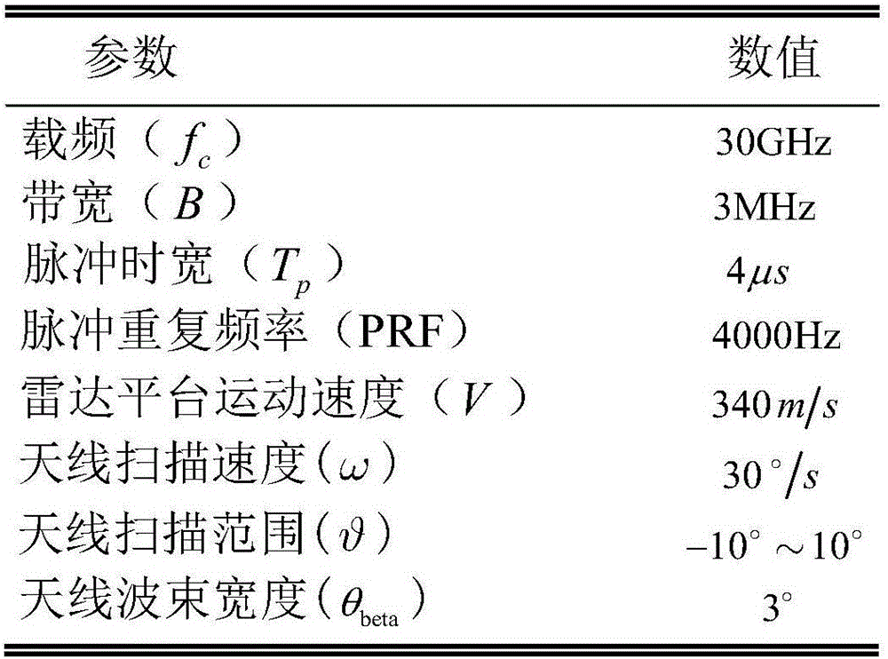
[0091] Such as figure 1 As shown, the radar angle super-resolution method selected by the optimal antenna pattern of the present invention adopts such as figure 2 The forward-looking scanning radar imaging movement geometry model is shown, and the scanning radar imaging parameters are as follows: image 3 shown. The target scenarios adopted by this scheme are as follows: Figure 5 shown. Including the following steps:

[0092] Step 1, forward-looking scanning radar azimuth echo modeling; in the step 1, the forward-looking scanning radar azimuth echo modeling process is, because based on the airborne radar, the speed of the carrier aircraft platform is V; the scanning speed of the radar antenna is ω; beam elevation angle is θ; target azimuth angle is The initial slant distance from the target to the radar antenna in the scene is denoted...


PUM


Abstract

The invention discloses an optimal antenna directional diagram selection radar angular super-resolution method comprising the steps of forward-looking scanning radar azimuth echo modeling; echo data distance direction pulse compression; range walk judgment; range walk correction; a scanning radar angular azimuth direction echo convolution model; and deconvolution performed based on optimal antenna directional diagram selection. The last step includes formula deviation: threshold is set and a cut-off position is controlled; point number Ncha is changed and width is controlled so that an antenna directional diagram is obtained; the antenna directional diagram is substituted in a deviation formula for convolution inversion so that an inversion result diagram is obtained; image entropy is calculated and the antenna directional diagram is confirmed; and a final result is obtained through calculation. The beneficial effects of the method are that influence of error of the antenna directional diagram on the convolution inversion result is analyzed from the angle of algebra firstly, then the optimal antenna directional diagram is confirmed based on the method of image entropy, and the optimal antenna directional diagram is substituted in the deconvolution method so that the solution of a convolution inversion problem can be realized, and scanning radar angular super-resolution imaging can be realized.

Description

technical field [0001] The invention belongs to the technical field of radar signal processing, in particular to scanning radar angle super-resolution imaging. Background technique [0002] As an important means of information acquisition, radar imaging technology is playing an increasingly important role in many fields such as military and civilian. In particular, the radar imaging directly in front of the aircraft has urgent application requirements in the fields of fighter planes' ground reconnaissance and attack, blind landing navigation, and missile precision terminal guidance. [0003] Real-beam scanning radar can achieve range-up super-resolution by transmitting a chirp signal with a large time-width-bandwidth product, but the azimuth resolution is limited by the wavelength and antenna aperture parameters. The angular resolution of the scanning radar antenna is where λ is the radar wavelength and D is the size of the antenna aperture. Therefore, the most direct wa...

Claims


Application Information

Patent Timeline
Patent Type & Authority Applications(China)
IPC IPC(8): G01S7/41G01S13/89G01S13/28
CPCG01S7/41G01S13/282G01S13/89
Inventor 黄钰林王月周小军任建宇张永超杨建宇
Owner UNIV OF ELECTRONICS SCI & TECH OF CHINA
Why Eureka
Try Eureka