Electronic module and electronic system

A technology of electronic modules and electronic systems, applied in the direction of electrical components, electrical digital data processing, instruments, etc., can solve the problems of large size and fixed shape of electronic modules, and achieve the effect of convenient and flexible connection and easy communication

Inactive Publication Date: 2015-12-09
PANOWIN TECH
View PDF2 Cites 1 Cited by
  • Summary
  • Abstract
  • Description
  • Claims
  • Application Information

AI Technical Summary

Problems solved by technology

[0007] Existing electronic systems connect electronic modules together in the form of connecting wires, and the unified interface also makes the appearance of electronic modules relatively fixed and bulky

Method used


Image

  • Electronic module and electronic system
  • Electronic module and electronic system
  • Electronic module and electronic system

Examples


no. 1 example

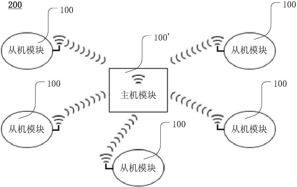
[0054] In the first embodiment, the electronic system provided by the present invention includes a master module 300' and a slave module 300A.

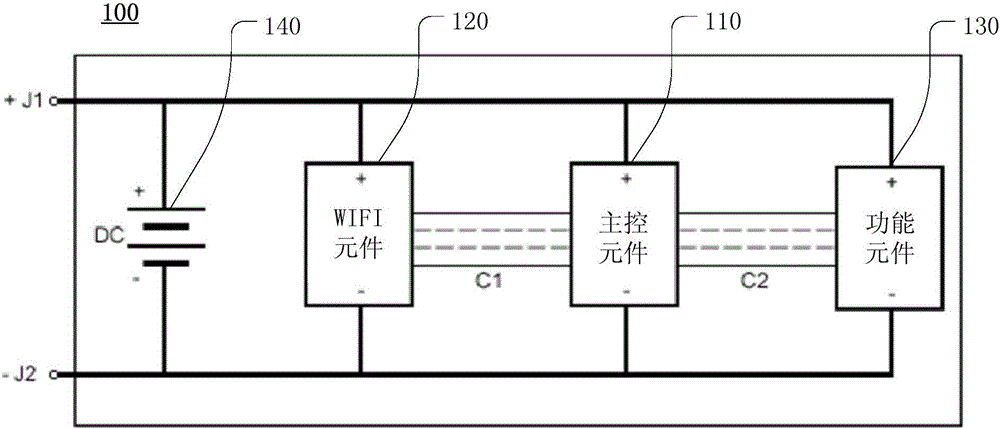
[0055] For the structure of the host module 300’ see Figure 5 , Which includes a main control chip, a power supply 340, a flash memory element (FLASH) 350, and a program writer (Programmer) 360.

[0056] The main control chip integrates the main control element 310 and the WIFI element 320. The main control chip can communicate externally through the GPIO interface 313 (GeneralPurposeInputOutput), the UART interface 312 (UniversalAsynchronousReceiver / Transmitter) and the SPI interface 311 (SerialPeripheralInterface). Preferably, the main control chip may be a chip with a model number of ESP8266.

[0057] The power supply 340 can use a CR2032 button battery to provide the 3.3V DC voltage required by the host module 300. The power supply 340 in this embodiment selects a button battery, and the battery is replaced to maintain the continuous ...

no. 2 example

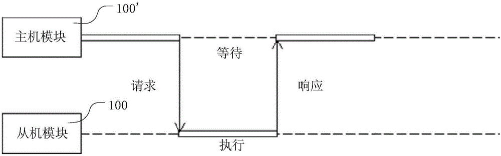
[0084] The electronic system includes a master module 300', a slave module 300A and a slave module 300B. The HTTP control interfaces of the master module 300', the slave module 300A, and the slave module 300A are the same as those of the first embodiment, and will not be repeated here.

[0085] See Figure 7 The slave module 300B adds a functional element 330B to the master module 300'. The functional element 330B includes a light sensing functional element. The light sensor function element is a photosensitive element based on a photosensitive resistor. Only after the configuration of the light-sensing functional components can they return different signals to the GPIO pin 313 of the main control chip according to the brightness of the ambient light.

[0086] The received request URL address of the slave module 300B is:

[0087] http: / / ip address / read-light

[0088] After receiving the request, the slave module 300B reads the signal of the photoresistor, converts it into an intege...


PUM


Abstract

The invention provides an electronic module and an electronic system. The electronic module comprises a WiFi (wireless fidelity) element, a function element, a main control element and a power supply, wherein the WiFi element is set to communicate with another or more electronic modules through a WiFi network; the function element is set to execute functions; the main control element is coupled with the WiFi element and the function element and controls the WiFi element and the function element; the power supply supplies power to the electronic module. According to the electronic module and the electronic system, connection between the electronic modules is more convenient and flexible.

Description

Technical field [0001] The present invention relates to the field of electronic modules, in particular to an electronic module and an electronic system communicating through WIFI. Background technique [0002] An electronic system is usually composed of multiple components, and the components communicate with each other to jointly complete the preset goals of the system. Industrial production generally uses circuit boards (soldering components on an insulating bottom plate, and the components are connected by conductors) and integrated circuits (packaged components into chips) to achieve this goal. Although this method is stable and efficient, it is costly and lacks flexibility. Therefore, in experiments and educational practices, electronic modules will be used. [0003] The electronic module is to solder one or more components that realize a certain function on the circuit board, and at the same time, there will be sockets for one or more wires on the circuit board. Multiple e...

Claims


Application Information

Patent Timeline
IPC IPC(8): G06F15/163H04W88/02
Inventor 潘敬华刘海川季明林进发
Owner PANOWIN TECH
Why Eureka
Try Eureka