
Low-pressure casting mould and method for casting hub

A low-pressure casting and mold technology, applied in the field of molds, can solve the problems of complex aluminum alloy wheel technology, single spoke shape, high equipment cost, etc., and achieve the effects of shortening the filling time, high equipment precision, and low cost

Active Publication Date: 2015-12-16
ZHEJIANG JINFEI KAIDA WHEEL
View PDF7 Cites 13 Cited by
  • Summary
  • Abstract
  • Description
  • Claims
  • Application Information

AI Technical Summary

Problems solved by technology

[0002] At present, the wheels of buses or trucks are mainly steel wheels and aluminum alloy forged spinning wheels, and steel wheels still occupy most of the market share. Development in the direction of quantification; many trucks have begun to eliminate heavy steel wheels and choose lighter aluminum alloy wheels. Higher requirements are put forward. In addition to requiring a certain strength, it also requires high corrosion resistance and fatigue resistance. Therefore, the existing truck hubs are all forged by using aluminum alloy round bars and using large-tonnage forging presses. Spinning blanks, and then use spinning machines to spin rims, the production of forged aluminum alloy wheels is complex, the shape of the spokes is single, and the equipment cost is high, which is not conducive to market competition of products. Therefore, for the load characteristics of truck or bus wheel hubs , it is very important to design a truck hub low pressure casting mold

Method used


Image

  • Low-pressure casting mould and method for casting hub
  • Low-pressure casting mould and method for casting hub
  • Low-pressure casting mould and method for casting hub

Examples


Embodiment Construction

[0037] In order to understand the above-mentioned purpose, features and advantages of the present invention more clearly, the present invention will be further described in detail below in conjunction with the accompanying drawings and specific embodiments. It should be noted that, in the case of no conflict, the embodiments of the present application and the features in the embodiments can be combined with each other.

[0038] In the following description, many specific details are set forth in order to fully understand the present invention. However, the present invention can also be implemented in other ways different from those described here. Therefore, the protection scope of the present invention is not limited by the specific details disclosed below. EXAMPLE LIMITATIONS.

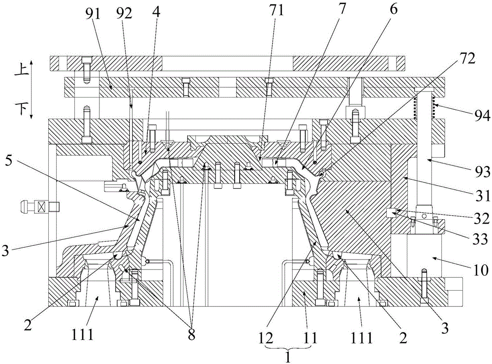
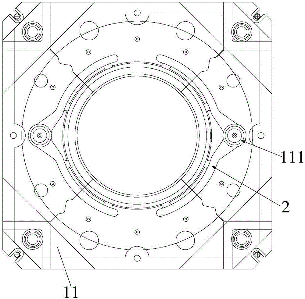
[0039] Refer below figure 1 with figure 2 The low pressure casting mold according to some embodiments of the present invention is described.

[0040] Such as figure 1 with figure 2 As shown, t...


PUM


Abstract

The invention provides a low-pressure casting mould and a method for casting a hub. The low-pressure casting mould comprises a lower mould body, multiple side mould bodies, an upper mould body and a control device. The multiple side mould bodies are matched with the lower mould body to form a rim cavity and a flow pass cavity corresponding to a rim of the hub to be cast. The upper mould body is matched with the lower mould body and the side mould bodies to form a spoke cavity corresponding to a spoke of the hub to be cast, an installing cavity corresponding to an installing plate of the hub to be cast, and an upper wheel edge cavity corresponding to an upper wheel lip of the hub to be cast. Two sprue cavities are formed in a bottom plate. The flow pass cavity, the upper wheel edge cavity, the spoke cavity, the rim cavity and the installing cavity are communicated mutually to form a cavity of the hub to be cast. The cavity of the hub to be cast is communicated with the two sprue cavities. According to the low-pressure casting mould, materials are fed from the two sprue cavities, casting to the top is carried out, mould filling time is shortened, stability is good, low-pressure casting is adopted for replacing forging to obtain a rotary extruded workblank, compared with forging equipment, precision is higher, manufacturing cost is lower, the mechanical performance of products is improved, and the production cost is reduced, which is beneficial for market competitiveness of the products.

Description

technical field [0001] The invention relates to the field of molds, in particular to a low-pressure casting mold and a method for casting a wheel hub using the mold. Background technique [0002] At present, the wheels of buses or trucks are mainly steel wheels and aluminum alloy forged spinning wheels, and steel wheels still occupy most of the market share. Development in the direction of quantification; many trucks have begun to eliminate heavy steel wheels and choose lighter aluminum alloy wheels. Higher requirements are put forward. In addition to requiring a certain strength, it also requires high corrosion resistance and fatigue resistance. Therefore, the existing truck hubs are all forged by using aluminum alloy round bars and using large-tonnage forging presses. Spinning blanks, and then use spinning machines to spin rims, the production of forged aluminum alloy wheels is complex, the shape of the spokes is single, and the equipment cost is high, which is not conduc...

Claims


Application Information

Patent Timeline
Patent Type & Authority Applications(China)
IPC IPC(8): B22D18/04
Inventor 王健李建生唐海军李嘉李振华
Owner ZHEJIANG JINFEI KAIDA WHEEL
Learn More