Clamping device for annular forgings

A clamping device and a technology for annular forgings, applied in the field of forging machinery, can solve the problems of complex structure and cumbersome clamping procedures, and achieve the effects of convenient clamping and positioning and simple structure.

Inactive Publication Date: 2015-12-16
AVIC EXCELLENCE FORGING WUXI
8 Cites 0 Cited by

AI-Extracted Technical Summary

Problems solved by technology

The ring forging positioning device in the prior art has a com...

Method used

[0017] The pillar 2 and the annular tray base 1 are integrally arranged, which improves the...

Abstract

The invention discloses a clamping device for annular forgings. The clamping device for the annular forgings comprises an annular tray base, a supporting column and a support backing plate installed on the supporting column are arranged in the center of the tray base, guide lifting rods are evenly distributed on the circumferential edge of the annular tray base, the bottom of each guide lifting rod is installed on a lifting cylinder, and the top of each guide lifting rod is further provided with a fixture body. In this way, according to the clamping device for the annular forgings, the structure is simple, clamping and positioning are convenient, the annular forgings can be firmly supported, the annular forgings can be tightly pressed or loosened, and the firm positioning function on the annular forgings is achieved.

Application Domain

Work clamping meansPositioning apparatus +2

Technology Topic

EngineeringForging

Image

  • Clamping device for annular forgings

Examples

  • Experimental program(1)

Example Embodiment

[0014] The technical solutions in the embodiments of the present invention will be described clearly and completely below. Obviously, the described embodiments are only a part of the embodiments of the present invention, rather than all the embodiments. Based on the embodiments of the present invention, all other embodiments obtained by those of ordinary skill in the art without creative work shall fall within the protection scope of the present invention.
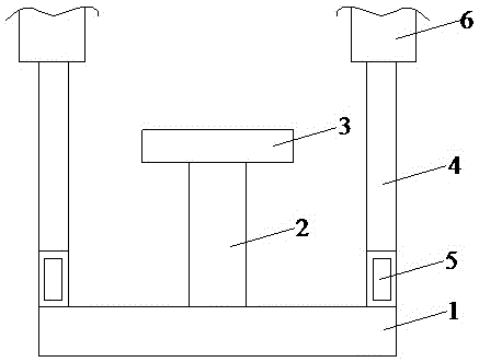
[0015] See figure 1 , The embodiment of the present invention includes:
[0016] A clamping device for an annular forging includes an annular pallet base 1, a pillar 2 and a supporting pad 3 installed on the pillar 2 are provided in the center of the pallet base 1.
[0017] The pillars 2 and the annular tray base 1 are integrally arranged, which improves the supporting capacity of the annular tray base 1 and can support the annular forgings stably.
[0018] The supporting pad 3 can be installed on the pillar 2 in a horizontal direction or a vertical direction, and the actual installation direction is matched with the processing requirements of the annular forging, which meets the actual processing requirements.
[0019] A guide pull rod 4 is evenly distributed on the circumferential edge of the annular tray base 1, and the bottom of the guide pull rod 4 is installed on a lifting cylinder 5.
[0020] Specifically, the annular tray base 1 is provided with a through hole, and the piston rod of the lifting cylinder 5 passes through the through hole. In this way, it is guaranteed that the lifting cylinder can be replaced without being restricted by the diameter of the ring forging.
[0021] The top of the guiding pull rod 4 is also provided with a clamping body 6, and the clamping body 6 performs a reciprocating movement under the action of the lifting cylinder 5 and the guiding pull rod 4.
[0022] The clamp body 6 can compress or loosen the ring forging under the driving of the lifting cylinder 5 and the guiding pull rod 4, and play a role of stabilizing and fixing the ring forging.
[0023] The beneficial effects of the clamping device for annular forgings of the present invention are:
[0024] The structure is simple, the clamping and positioning is convenient, the annular forging can be firmly supported, and the annular forging can be compressed or loosened, and the annular forging can be stabilized and fixed.
[0025] The above are only the embodiments of the present invention and do not therefore limit the scope of the present invention. Any equivalent structure or equivalent process transformation made by using the content of the present invention description, or directly or indirectly applied in other related technical fields, are all The same reason is included in the scope of patent protection of the present invention.

PUM

no PUM

Description & Claims & Application Information

We can also present the details of the Description, Claims and Application information to help users get a comprehensive understanding of the technical details of the patent, such as background art, summary of invention, brief description of drawings, description of embodiments, and other original content. On the other hand, users can also determine the specific scope of protection of the technology through the list of claims; as well as understand the changes in the life cycle of the technology with the presentation of the patent timeline. Login to view more.

Similar technology patents

Body condition measuring device

InactiveUS20050234351A1simple structure
Owner:DENSO CORP

Magnetic cooling apparatus and control method thereof

ActiveUS20130180263A1simple structure
Owner:SAMSUNG ELECTRONICS CO LTD

Dual-Drivetrain of Power-Assist Vehicle

InactiveUS20100181130A1enhance uphill momentumsimple structure
Owner:CHOU WEN CHENG

Classification and recommendation of technical efficacy words

  • Simple structure
  • Easy clamping and positioning

Sharing system for air-conditioning coat

InactiveCN107440179ASimple structureeasy to wear
Owner:QINGDAO HAIER AIR CONDITIONER GENERAL CORP LTD

Feeding device of sorter of batteries plate

InactiveCN101357717ASimple structurecooperate well
Owner:NANJING NORMAL UNIVERSITY

Emergency parachuting device and method for multiple-rotor unmanned aerial vehicle

InactiveCN103895870Aavoid aircraft crashSimple structure
Owner:SOUTH CHINA AGRI UNIV +1

Double-end automatic straight seam welding machine

InactiveCN102785000AEasy clamping and positioningImprove welding efficiency
Owner:DONGGUAN JIALONG LEATHER MACHIERY

Machining process of aero-engine blade

PendingCN113618127AGuaranteed machining accuracyEasy clamping and positioning
Owner:AECC AERO SCI & TECH CO LTD
Why Eureka
Try Eureka