Double-surface thicknessing machine

A planer, double-sided technology, applied in the field of planing machinery and double-sided planers, can solve the problems of insufficient space for planers, difficult disassembly and assembly, etc., and achieves simple and novel structure, convenient disassembly and maintenance, and improved replacement speed and assembly. The effect of knife accuracy

Inactive Publication Date: 2015-12-16
ANJI DEMAI BAMBOO & WOOD MACHINERY
View PDF13 Cites 3 Cited by
  • Summary
  • Abstract
  • Description
  • Claims
  • Application Information

AI Technical Summary

Problems solved by technology

[0004] The purpose of the present invention is to provide a double-sided planer to so

Method used


Image

  • Double-surface thicknessing machine
  • Double-surface thicknessing machine
  • Double-surface thicknessing machine

Examples


Embodiment 1

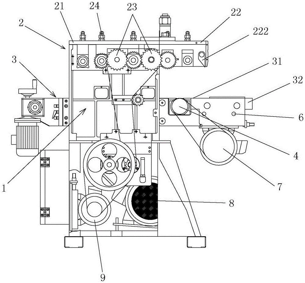
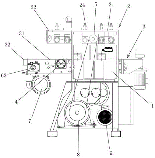
[0026] Example 1: Such as Figure 1-2 As shown, a double-sided planer includes a frame 1, a fixed table 2 and a lifting table 3. The frame 1 is fixed relative to the ground, the fixed platform 2 is installed on the upper part of the frame 1, the lifting platform 3 is installed on the frame 1 in a liftable manner, and the lifting platform 3 is located below the fixed platform 2.

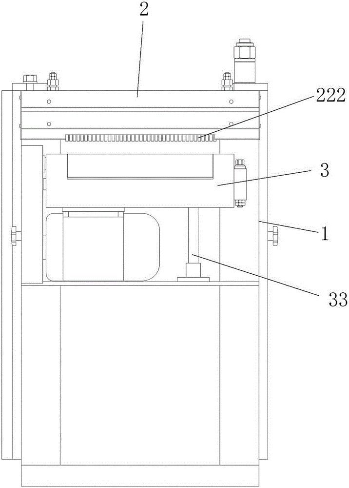
[0027] Specifically, the lifting platform 3 is lifted as follows: image 3 As shown, the bottom of the lifting platform 3 is provided with a lifting mechanism 33, which includes a lifting motor, a lifting screw and a screw nut. The reduction motor drives the lifting screw to rotate in a controlled manner, so that the screw nut drives the lifting platform 3 to lift.

[0028] Such as figure 1 As shown, the lifting platform 3 is provided with a lower planing knife 4, which is driven to rotate by a first driving motor 7 fixed on the lifting platform 3.

[0029] Such as figure 2 As shown, the fixed table 2 is p...

Embodiment 2

[0038] Embodiment 2: Basically the same as Embodiment 1, the following planing knife 4 is set on the lifting platform 3 and located below the rotating table 22; the difference from Embodiment 1 is that the fixed table body 21 and the rotating table 22 are hinged The shaft is connected, so that the rotating table 22 can be opened or flipped open relative to the fixed table body 21, similar to a book. When the rotating table 22 is turned over, an operating area is formed above the lower planing knife 4, so that there is sufficient operating space when the lower planing knife 4 is disassembled and assembled.

Embodiment 3

[0039] Embodiment 3: Basically the same as embodiment 1, the following planing knife 4 is set on the lifting table 3 and located below the rotating table 22; the difference from embodiment 1 is that the fixed table body 21 and the rotating table 22 are The ends of the connecting ends are all provided with connecting plates, and the connecting plate on the fixed table body 21 and the connecting plate on the rotating table 22 are fastened and connected by fasteners, thereby connecting the fixed table body 21 and the rotating table 22 into one body. When the lower planing knife 4 needs to be disassembled, first remove the fasteners on the connecting plate to separate the rotating table 22 from the fixed table body. At this time, an operation area is formed above the lower planing knife 4 to make the disassembly and assembly There is enough space for operation. Here, the rotating table 22 is not a rotating table, but it is simply called according to the situation to distinguish the...


PUM


Abstract

The invention discloses a double-surface thicknessing machine, particularly relates to a double-sided thicknessing machine capable of thicknessing both the upper surface and the lower surface of woods and belongs to the technical field of wood-working machines. The double-surface thicknessing machine comprises two parts which are used for applying pressure in two corresponding directions to generate clamping effect during working, wherein a first thicknessing cutter is arranged on one part; a second thickenssing cutter is arranged on the other part; at least one of the two parts is provided with a workpiece pushing mechanism, so that the workpieces are relatively fixed all the time in the process of being thickenssed; at least one part is a split structure; the split structure is split to form an operation area for conveniently assembling and disassembling the thicknessing cutters relative to the other part. The double-surface thicknessing machine is simple and novel in structure, simple to operate and convenient to use; a feeding roller can be removed from the upper part of the lower thickenssing cutter by just rotating a rotation table to a certain angle; the enough space is provided for assembling and disassembling the lower thickenssing cutter; the double-surface thicknessing machine is convenient to assemble, disassemble and repair; the labor intensity of workers is reduced; the replacement speed and the cutter assembling accuracy are improved.

Description

technical field [0001] The invention discloses a planing machine, in particular to a double-sided planer capable of planing wood on both sides up and down, and belongs to the technical field of woodworking machinery. Background technique [0002] A planer is an automatic processing machine that uses a planer to plan wood. According to different technological uses, woodworking planers can be divided into flat planers, single-sided planers, double-sided planers, three-sided planers, four-sided planers and polished planers. In the prior art, a double-sided planer is composed of a body, a workbench, an upper planer, a lower planer, a feed roller and a discharge roller. During the continuous planing process, the upper planer and the lower planer are easy to wear and need to be polished and replaced regularly, and because there is a feed roller above the lower planer, the space above the lower planer is very small, making it inconvenient to disassemble and assemble the lower plane...

Claims


Application Information

Patent Timeline
IPC IPC(8): B27C1/04B27C1/14B27C1/12
Inventor 马明海
Owner ANJI DEMAI BAMBOO & WOOD MACHINERY
Why Eureka
Try Eureka