A differential drive mechanism for rudder surface suitable for unmanned aerial vehicles

A differential drive and drive mechanism technology, applied in the direction of non-power amplification, aircraft transmission, aircraft power transmission, etc., can solve the problem of low transmission efficiency, reduce control difficulty, save manufacturing costs, and improve control accuracy.

Active Publication Date: 2018-04-27
CHINA ACAD OF LAUNCH VEHICLE TECH
View PDF4 Cites 0 Cited by
  • Summary
  • Abstract
  • Description
  • Claims
  • Application Information

AI Technical Summary

Problems solved by technology

Also due to the use of two-stage transmission, the transmission efficiency is not high, and what is achieved is the flapping of the wing up and down, which is far from the purpose of the UAV aileron rotating around the axis.

Method used


Image

  • A differential drive mechanism for rudder surface suitable for unmanned aerial vehicles
  • A differential drive mechanism for rudder surface suitable for unmanned aerial vehicles
  • A differential drive mechanism for rudder surface suitable for unmanned aerial vehicles

Examples


Embodiment Construction

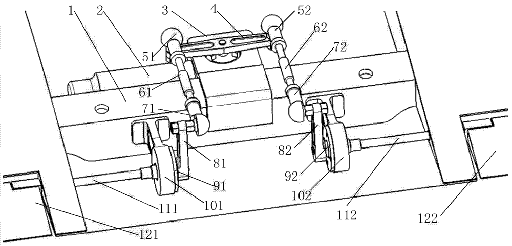
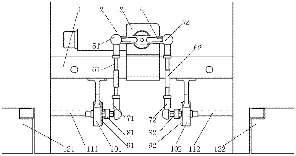
[0023] Such as figure 1 , figure 2 As shown, a rudder surface differential drive mechanism suitable for unmanned aerial vehicles includes: a common module, a left aileron drive mechanism module, and a right aileron drive mechanism module; the shared module includes a wing main beam 1, an electric steering gear 2. Steering gear base 3, dual output steering gear connecting rod 4; the left aileron drive mechanism module includes the left first ball joint rod end joint bearing 51, the left connecting rod 61, and the left second ball joint rod end joint bearing 71. The left rudder shaft connecting rod 81, the left bearing end cover 91, the left bearing seat 101, the left aileron rudder shaft 111; Side connecting rod 62 , right side second ball joint rod end joint bearing 72 , right side rudder shaft connecting rod 82 , right side bearing end cover 92 , right side bearing seat 102 , right aileron rudder shaft 112 .

[0024] The power source electric steering gear 2 of the rudder ...


PUM


Abstract

A rudder surface differential drive mechanism suitable for unmanned aerial vehicles, comprising: a shared module, a left aileron drive mechanism module, and a right aileron drive mechanism module; an electric steering gear (2) drives a dual-output steering gear linkage (4) to rotate , the left aileron rudder shaft (111), the left aileron rudder shaft (111), The right aileron rudder shaft (112) rotates in the opposite direction, so that the left aileron (121) and the right aileron (122) deflect in reverse. The present invention adopts the dual RSSR space four-link combination mechanism to realize the differential drive to the left aileron and the right aileron, solves the synchronization problem of the left aileron and the right aileron movement, and realizes the movement of the left aileron and the right aileron, etc. High-speed transmission, while reducing the requirements for machining accuracy and tooling, saving manufacturing costs.

Description

technical field [0001] The invention relates to a rudder surface differential driving mechanism. Background technique [0002] The left and right ailerons of the UAV are symmetrically arranged on the trailing edge of the left and right wings, and are used to adjust the flight attitude of the UAV. When the left and right ailerons are neutral, the UAV is in level flight; When deflecting (differential), the drone rolls. As the mechanical transmission device of the aileron, the driving mechanism is connected to the electric steering gear of the power source on the one hand, and the aileron rudder surface of the actuator on the other hand, so as to convert the rotational motion of the electric steering gear into the deflection motion of the aileron around the rudder axis. According to the flight attitude control requirements of UAVs, the left and right ailerons are only used to control the roll of the aircraft, and the drive mechanism needs to differentially drive the left and r...

Claims


Application Information

Patent Timeline
Patent Type & Authority Patents(China)
IPC IPC(8): B64C13/28B64C13/50
Inventor 宋春雨彭波王悦张涛贾磊穆星科徐方舟孔文秦张庆利王涛石小亮
Owner CHINA ACAD OF LAUNCH VEHICLE TECH
Why Eureka
Try Eureka