Feeding device

A technology of feeding device and coiling material, applied in the direction of conveying filamentous materials, thin material handling, transportation and packaging, etc., can solve problems such as inconvenience of operation, and achieve the effect of saving time and labor, easy operation and reducing resistance.

Inactive Publication Date: 2015-12-16
CHONGQING YUKUNLONG METALLURGICAL MATERIAL CO LTD
View PDF0 Cites 5 Cited by
  • Summary
  • Abstract
  • Description
  • Claims
  • Application Information

AI Technical Summary

Problems solved by technology

[0004] The present invention intends to provide a feeding device to solve the problem of inconvenient operation of the existing feeding device because the coil material loading and unloading structure is higher than the ground

Method used


Image

  • Feeding device
  • Feeding device
  • Feeding device

Examples


Embodiment Construction

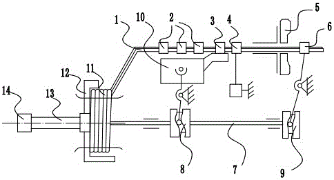
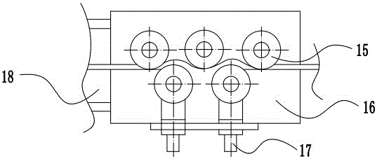
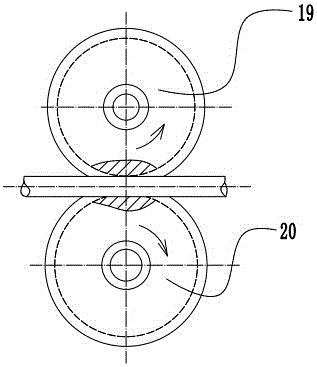
[0021] The reference signs in the drawings of the description include: workbench 1, straightening mechanism 2, transmission mechanism 3, front chuck 4, rotary knife 5, rear chuck 6, camshaft 7, first cam 8, second cam 9 , shift fork body 10, coil material 11, support plate 12, rotating shaft 13, motor 14, fixed pin 15, slide plate 16, adjustment screw 17, guide rail 18, first roller 19, second roller 20, jaw 21, first Spring 22, third cam 23, fixed block 24, slide block 25, second spring 26.

[0022] like figure 1 As shown, a feeding device includes a motor 14, a rotating shaft 13 connected to the motor 14, a support disc 12 screwed to the rotating shaft 13, the support disc 12 is a vertically placed cylindrical groove, and the center of the support disc 12 is socketed There is a camshaft 7, and the coil material 11 is placed on the supporting disk 12 and then the camshaft 7 is sleeved on the supporting disk 12. One end of the coil material 11 is drawn to three straightening...


PUM


Abstract

The invention discloses a feeding device, and relates to the field of auxiliary machining. The feeding device comprises a workbench, a motor, a rotating shaft connected with the motor, and a supporting disc connected with the rotating shaft and used for a coil stock to be placed. The end, close to the coil stock, of the workbench is an inclined face, and the end, far away from the coil stock, of the workbench is horizontally arranged. A straightening mechanism, a conveying mechanism, a front clamping head, a rotation cutter and a rear clamping head are sequentially arranged at the horizontal position of the workbench. The supporting disc is of a cylindrical structure with the axis being horizontal. The circle center of the supporting disc is detachably connected with a cam shaft. The cam shaft is sequentially provided with a first cam and a second cam which are provided with a first lever and a second lever respectively. A forklift body is arranged between the first lever and the conveying mechanism and can shift the conveying mechanism to move left and right according to the movement of the first lever. The second lever is connected with the rear clamping head. The feeding device is simple in structure and convenient to operate.

Description

technical field [0001] The invention relates to the field of auxiliary processing, in particular to a feeding device. Background technique [0002] Coils refer to metal or plastic materials rolled into barrels. In production and processing, coils are usually used as raw materials for production and processing. In the process of processing, it is usually necessary to uncoil the coiled material, and transfer the uncoiled coiled material to the corresponding station for processing through the transmission device. After the processing is completed, it is necessary to seal the remaining coiled material so that Continue to use it next time. [0003] The place where the coil material is placed in the current feeding device is generally higher than the ground, and because the coil material is generally large in size and heavy in weight, the on-line and off-line of the coil material must be realized by a crane, and the uncoil and In the process of sealing the coil, it is also nece...

Claims


Application Information

Patent Timeline
Patent Type & Authority Applications(China)
IPC IPC(8): B65H49/26B65H49/36B65H51/18
Inventor 罗静李炎清王学清
Owner CHONGQING YUKUNLONG METALLURGICAL MATERIAL CO LTD
Why Eureka
Try Eureka