
a drying device

A drying device and drying chamber technology, applied in the direction of dehydration/drying/concentrated sludge treatment, etc., can solve the problems of difficulty in landfill, large volume and weight of sludge, and low efficiency, so as to improve the utilization rate of heat energy and improve the efficiency. Practical value, effect of improving efficiency

Active Publication Date: 2017-04-12
FUJIAN QINGDAOFU ENVIRONMENTAL PROTECTION TECH
View PDF4 Cites 0 Cited by
  • Summary
  • Abstract
  • Description
  • Claims
  • Application Information

AI Technical Summary

Problems solved by technology

[0002] After the sewage treatment plant treats the sewage, the rest is sludge. Due to the process of sewage treatment, it is very difficult to dry the sludge. The existing process is to dry it to about 60~70% for landfill This treatment method will not only cause groundwater pollution, but also the volume and weight of the sludge is large, making it difficult to landfill
Although there are many sludge drying technologies, their efficiency is not high, and because the existing sludge drying tanks are designed horizontally, it not only takes up space, but also due to the gravity of the sludge itself, it is centrifuged in a horizontal boiler. Drying will lead to uneven drying of the sludge, and after the sludge is dried to 50%, the sludge contains cell blisters, the traditional process is difficult to further dry it, and consumes a lot of energy

Method used


Image

  • a drying device
  • a drying device

Examples


Embodiment Construction

[0014] In order to make the above-mentioned features and advantages of the present invention more comprehensible, the following specific embodiments are described in detail with reference to the accompanying drawings.

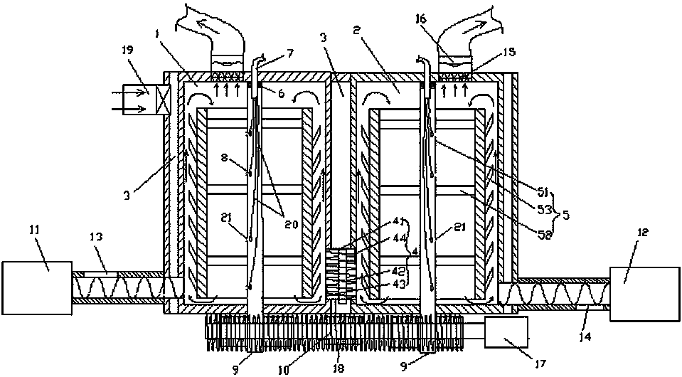
[0015] See figure 1 , this embodiment provides a drying device, which includes a first drying cavity 1 and a second drying cavity 2, the first drying cavity 1 and the second drying cavity 2 are integrated in a heating In the cavity 3, and the adjacent side walls of the first drying cavity and the second drying cavity are provided with a transfer device for transferring the sludge in the first drying cavity to the second drying cavity 4. Both the first drying cavity and the second drying cavity are provided with a drum 5 for realizing the spiral lifting of the materials in the tank. In this embodiment, the heating chamber has a heat source inlet 19 .

[0016] In one embodiment of the present invention, the material transfer device 4 includes a columnar cavity ...


PUM


Abstract

The invention relates to a drying device. The drying device is characterized by comprising a first drying cavity and a second drying cavity, wherein the first drying cavity and the second drying cavity are integrated in a heating cavity, and adjacent side walls of the first drying cavity and second drying cavity are provided with a transferring device for transferring the sludge in the first drying cavity into the second drying cavity; both the first drying cavity and the second drying cavity are respectively internally provided with a rotary drum for spirally hoisting a material in a tank body. The drying device is simple in structure; two tank body structures are contained in one heating cavity, so that not only can the technical leakage caused by the exposure of the existing vertical tank body to people be overcome, but also the energy can be effectively utilized, and the drying efficiency is improved.

Description

technical field [0001] The invention relates to a drying device, in particular to the technical field of sludge treatment. Background technique [0002] After the sewage treatment plant treats the sewage, the rest is sludge. Due to the process of sewage treatment, it is very difficult to dry the sludge. The existing process is to dry it to about 60~70% for landfill This treatment method will not only cause groundwater pollution, but also make it difficult to landfill due to the large volume and weight of the sludge. Although there are many sludge drying technologies, their efficiency is not high, and because the existing sludge drying tanks are designed horizontally, it not only takes up space, but also due to the gravity of the sludge itself, it is centrifuged in a horizontal boiler. The drying will lead to uneven drying of the sludge. In addition, after the sludge is dried to 50%, the sludge contains cell blisters. The traditional process is difficult to further dry it an...

Claims


Application Information

Patent Timeline
Patent Type & Authority Patents(China)
IPC IPC(8): C02F11/12
Inventor 刘建津
Owner FUJIAN QINGDAOFU ENVIRONMENTAL PROTECTION TECH
Learn More