Rotation piston pump

A piston pump and rotary technology, applied in the field of rotary piston pumps, can solve the problems that the intake and exhaust valves cannot be set too large, increase dynamic load and bearing wear, increase mechanical vibration, etc., and achieve simple manufacturing, The effect of low production cost and large output energy

Active Publication Date: 2015-12-16
庞乐钧
View PDF5 Cites 2 Cited by
  • Summary
  • Abstract
  • Description
  • Claims
  • Application Information

AI Technical Summary

Problems solved by technology

[0002] The existing reciprocating piston compression pump system has a complex structure and high power consumption. The piston, piston ring and cylinder are always in a side friction state, which increases the friction and increases the power loss. It is easy to make the cylinder out of round and cause sealing In addition, due to the influence of the area of ​​the top of the cylinder, the intake and exhaust valves cannot be set too large, which greatly limits the further improvement of performance.
At the same time, their complex crankshaft-connecting-rod mechanism and the reciprocating motion of the piston not only consume a lot of power, but also increase the dynamic load of each force-bearing part and the wear of the bearing due to the inertia of its complex motion, and increase the mechanical vibration, which seriously affects the speed increase

Method used


Image

  • Rotation piston pump
  • Rotation piston pump
  • Rotation piston pump

Examples


Embodiment approach 1

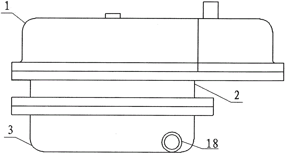
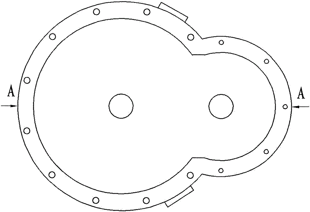
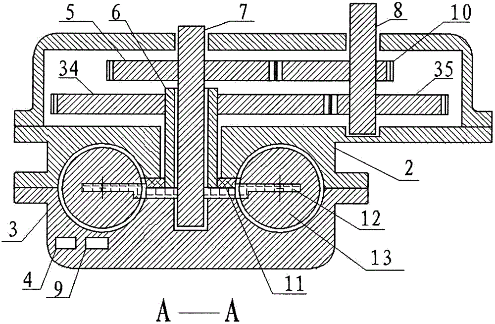
[0052] Implementation method 1: This structure includes two annular cylinders 2, 3 with semicircular inner sections to form a set of circular cylinders with a circular cross section, such as figure 1 , 2 , 3, 7, and 9; a sealing ring groove 33 is provided on the cylinder body where it contacts the rotor, such as Figure 7 , 9 Shown; Two rotors 11,12 are also housed in the cylinder body, the rotor is provided with seal block groove 24 and seal ring groove 25, seal block groove 24 inside is equipped with seal block 27, and seal ring groove 25,33 insides are all installed There is a sealing ring (not shown in the figure), and the sealing ring and the sealing block are provided with a spring function (not shown in the figure) to ensure the sealing effect; the rotor is equipped with rotor shafts 6 and 7, and the rotor shaft 6 is hollow and sleeved on the On the rotor shaft 7 and assembled with the rotor 11, the rotor shaft 7 passes through the rotor shaft 6 and the rotor 12 is as...

Embodiment approach 2

[0053] Implementation method 2: when acting on a liquid pump, the inner sections of the two annular cylinders 36, 37 can be set to be rectangular to form a set of annular cylinders with a rectangular section, and the four pistons 29 matched with them The cross-section is also rectangular, such as Figure 25 , 26 , Shown in 27 and 29; this implementation method does not need piston rings and lubrication mechanisms for piston rings; other than that, the others are the same as the implementation method one.

[0054] The working principle of this structure is as follows: it uses the difference in rotation angle between the two eccentric gears and the two non-circular gears to cause a difference in the rotation speed of the two rotors, so that the volume between the pistons changes, and the air intake and compression are completed. Exhaust is a coherent work procedure, its procedure is as follows Figure 14 , 20 , 24, 28, and 30, when setting and assembling, the non-circular gea...


PUM


Abstract

The invention discloses a rotation piston pump. The rotation piston pump is characterized in that an annular cylinder with the circular section is formed by two cylinder bodies with the semicircular inner sections and internally provided with two rotors, and four pistons are fixed to the two ends of the two rotors respectively; two non-circular gears are arranged on two rotor shafts respectively, two eccentric gears are installed on a power input shaft in the opposite direction, and the two non-circular gears and the two eccentric gears are engaged respectively to form two gear pairs; the lower cylinder body is internally provided with two air inlet holes and two air outlet holes; and acting of eight times is done every one-circle rotation of the pistons and is equal to acting circulation of rotation of four circles of a double-cylinder reciprocation type compressor crankshaft. The rotation piston pump is large in output energy, high in power and wide in application range.

Description

technical field [0001] The invention relates to a pump, in particular to a rotary piston pump. technical background [0002] The existing reciprocating piston compression pump system has a complex structure and high power consumption. The piston, piston ring and cylinder are always in a state of side friction, which increases the friction and increases the power loss. It is easy to make the cylinder out of round and cause sealing Not good, but also due to the impact of the cylinder head area, the intake and exhaust valves cannot be set too much, thus further improving the performance is greatly restricted. At the same time, their complex crankshaft-connecting-rod mechanism and the reciprocating motion of the piston not only consume a lot of power, but also increase the dynamic load of each force-bearing part and the wear of the bearing due to the inertia of its complex motion, and increase the mechanical vibration, which seriously affects the increase in speed. Contents o...

Claims


Application Information

Patent Timeline
Patent Type & Authority Applications(China)
IPC IPC(8): F04C2/00F04C15/00F04C15/06F04C18/00F04C29/00F04C29/12
Inventor 庞乐钧
Owner 庞乐钧
Why Eureka
Try Eureka