

Intermediate counter weight method for dynamic balance of elongated-shaft carbon fiber composite
A technology of composite materials and slender shafts, which is applied in the field of machining tooling to achieve the effect of solving deformation
Inactive Publication Date: 2015-12-16
ZIBO LANGDA COMPOSITE TECH
View PDF7 Cites 3 Cited by
- Summary
- Abstract
- Description
- Claims
- Application Information
AI Technical Summary
Problems solved by technology
[0003] In view of the above deficiencies in the prior art, the present invention provides a carbon fiber composite material dynamic balance intermediate counterweight method for a slender sha
Method used
View moreImage
Smart ImageViewing Examples

Examples
Embodiment Construction
[0015] The present invention will be described in detail below.
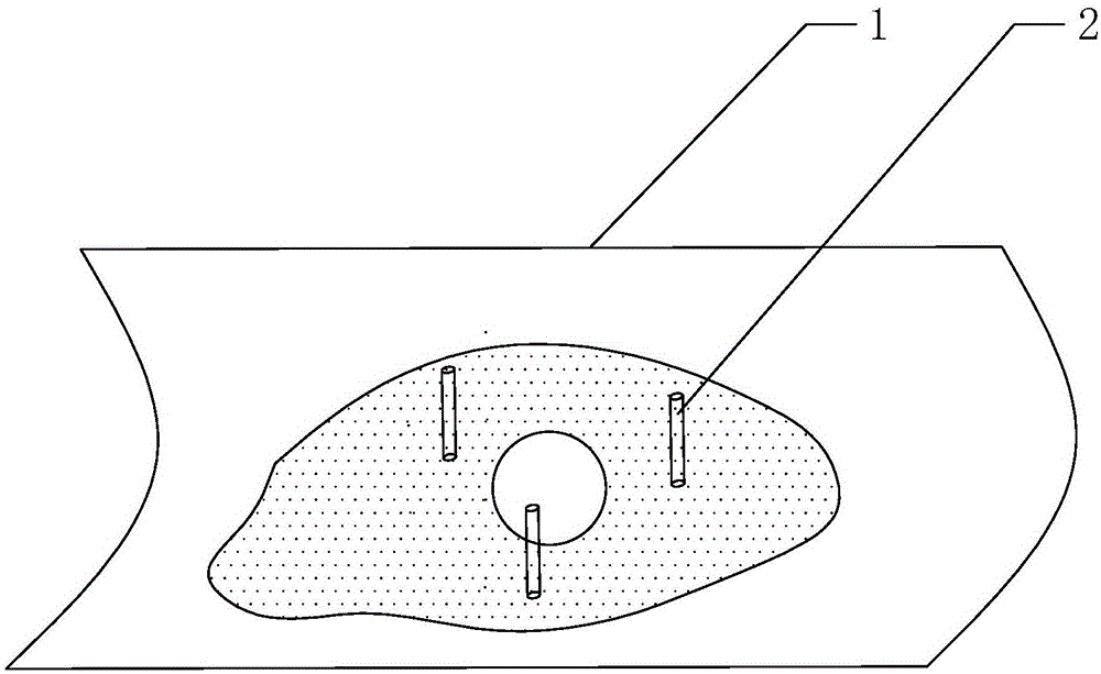
[0016] 1) Find the mechanical center of gravity of the slender shaft 1 through a dynamic balancing machine, and measure the counterweight;
[0017] 2) Use a 2mm drill bit to drill a hole at the center of gravity, then pour an appropriate amount of resin and iron powder into it for counterweight, and insert 1 to 3 small sticks 2 into the hole, which can act as a plug and penetrate deeply. In the carbon fiber roller, the role of fixed weight;
[0018] 3) Place the weighted slender shaft 1 horizontally with the hole facing down, and wait for the resin to solidify.
Login to View More PUM
 Abstract
The invention relates to an intermediate counter weight method for dynamic balance of an elongated-shaft carbon fiber composite and belongs to the technical field of machining tools. The method is characterized by comprising the following steps that firstly, a dynamic balancing machine is used for finding the mechanical gravity center of an elongated shaft and measuring the counter weight; secondly, the shaft is drilled to form a hole through a 2mm drill at the position of the gravity center, and an appropriate amount of resin and iron powder are poured into the hole for counter weighting; and thirdly, the counter-weighted elongated shaft is horizontally placed immovably with the hole downwards to wait for the curing of the resin. According to the method, the problem of deformation caused by certain elastic modulus of the carbon fiber composite during working is solved, and the rotation of the carbon fiber composite is more stable.
Description
technical field [0001] The invention relates to a method for dynamically balancing an intermediate counterweight of a slender shaft carbon fiber composite material, and belongs to the technical field of mechanical processing tooling. Background technique [0002] Carbon fiber is a new material with excellent mechanical properties. Its specific gravity is less than 1 / 4 of that of steel. The tensile strength of carbon fiber resin composite materials is generally above 3500MPa, which is 7 to 9 times that of steel. The tensile modulus of elasticity is 230 ~430MPa is also higher than steel. In the prior art, the use of carbon fiber composite materials is becoming more and more extensive. For example, the steel roller used in the past, although the length exceeds 10 meters, but the steel rod has high bending strength and does not need intermediate counterweights. It only needs counterweights at both ends of the steel rollers. Balance is enough, and the slender shaft carbon fiber ...
Claims
Login to View More Application Information
Patent Timeline
 IPC IPC(8): F16C3/02F16F15/10
Inventor刘鹏
OwnerZIBO LANGDA COMPOSITE TECH