Self-feedback damper device

A self-feedback, damper technology, applied in the direction of airflow control elements, etc., can solve the problems of inability to pull the windshield on demand, the normal operation of the damper is affected, and the installation of the damper is limited, etc. Compact, air leakage prevention effect

Inactive Publication Date: 2018-01-26
UNIV OF SHANGHAI FOR SCI & TECH
View PDF7 Cites 0 Cited by
  • Summary
  • Abstract
  • Description
  • Claims
  • Application Information

AI Technical Summary

Problems solved by technology

[0006] First, the air valve can only be used in places with gravity and the gravity is not determined, because the feedback wind receiving part of the air valve works under the action of wind force, gravity, rope tension and the pressure of the ventilation box on the wind receiving plate, weightlessness or In an environment with unstable gravity, the force breaks the balance, and the wind-receiving part cannot swing as required in the vertical plane, that is, the windshield cannot be pulled as required, and the air valve fails
[0007] Second, the air valve is not suitable for working in a vibrating environment, because in a vibrating environment, the wind-receiving part will shake left and right or up and down with the vibration, and cannot work normally
The second aspect is that the wind-receiving part will not stop immediately when it reaches a new balance point, it will swing around the balance point, which will appear when the wind speed increases and decreases rapidly, which will affect the normal work of the damper
[0009] Fourth, the installation of the air valve is limited, and it cannot be installed at any angle within 360 degrees. It must work normally in an environment where the wind receiving plate is vertically downward and the air box is placed horizontally.

Method used


Image

  • Self-feedback damper device
  • Self-feedback damper device
  • Self-feedback damper device

Examples


Embodiment Construction

[0031] The present invention will be further described below in conjunction with the accompanying drawings and embodiments.

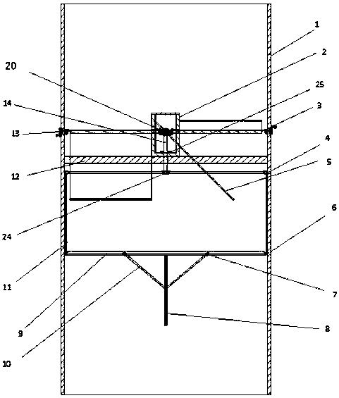
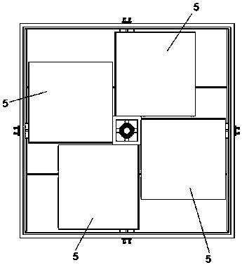
[0032] Such as Figure 1 to Figure 10 As shown, a self-feedback air valve device includes a box body 1, a wind deflector 5, a wind receiving plate 10, front and rear guide rails 8, left and right guide rails 9, ropes 11, connecting shaft 14, gear box 2, support frame 12, Rope groove 24, connecting rod 23, gear shaft positioning ring 25, sealing ring 3 etc. Four rotatable windshields 5 and the gear box 2 are installed in the front of the box body 1. The power output shaft of the gear box 2 is connected to the windshield 5, and the power input end of the gear box 2 is fixedly connected to the connecting shaft 14 and the gear shaft positioning ring. (25) and rope groove 24 ( Figure 10 ); the rear part of the box body 1 is equipped with a wind receiving plate 10.

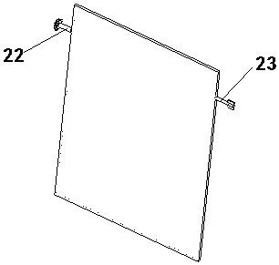
[0033] Such as Figure 5 As shown, the wind receiving plate 10 is made up of two plates,...


PUM


Abstract

The invention relates to a self-feedback air valve device. According to the device, four rotary wind shields and a gear case are arranged in the front portion of a box body, a power output shaft of the gear case is connected with a connecting rod of each wind shield, and the power input end of the gear case is fixedly connected with a connecting shaft and a rope groove; windward plates are arranged in the rear portion of the box body, the inner sides of the two windward plates are connected through a hinge in a rotary mode, and a spring is arranged below the hinge; guide rods are connected to the upper end of the inner side of each windward plate and to the upper end of the outer side of each windward plate respectively, the guide rods on the inner sides of the two windward plates are in sliding connection with a front guide rail and a rear guide rail which are fixed in the box body, and the guide rods on the outer sides of the two windward plates are in sliding connection with a left guide rail and a right guide rail which are fixed in the box body; the edges of the two windward plates are connected with a rope through holes in the windward plates, and the rope penetrates through two guiding holes in a fixed block on the box body to be connected with the rope groove in the rear end of the connecting shaft so as to drive the connecting shaft to rotate. The device is compact in structure, even in stress, orderly and continuous in movement, not affected by vibration of the working environment, accurate in transmission, high in precision, and capable of working in the vibrating environment.

Description

technical field [0001] The invention is an air valve, in particular a self-feedback control air valve device. Background technique [0002] Most of them now use manual air valves and electric air valves. Manual air valves are manually adjusted according to needs, and automatic control cannot be completed and the control is inaccurate. It is inconvenient to operate, control, and use, which will lead to productivity, quality, accuracy and low efficiency; [0003] The electric air valve is used as a gas medium to adjust the flow rate or cut off the device in the dusty cold air or hot air pipeline of the ventilation and environmental protection projects in the hardware, chemical, building materials, power station, glass and other industries. However, the operation of the electric air valve requires electric energy. Once the electric energy is lost, it can no longer work, and it is not energy-saving. Electric dampers generally cost more. [0004] The closest prior art has a pa...

Claims


Application Information

Patent Timeline
Patent Type & Authority Patents(China)
IPC IPC(8): F24F13/12
CPCF24F13/12
Inventor 黄政
Owner UNIV OF SHANGHAI FOR SCI & TECH
Why Eureka
Try Eureka