Counterforce loading frame for multifunctional self-balancing type continuous beam test

A reaction force loading, self-balancing technology, applied in measuring devices, instruments, scientific instruments, etc., can solve the problems of test error, complicated preparation, and difficulty, and achieve improved accuracy and convenience, convenient and fast installation, The effect of reducing manual labor

Active Publication Date: 2015-12-16
CHINA THREE GORGES UNIV
View PDF6 Cites 17 Cited by
  • Summary
  • Abstract
  • Description
  • Claims
  • Application Information

AI Technical Summary

Problems solved by technology

At present, the experimental research on beam components mainly focuses on simply supported beams, while the research on continuous beams is relatively scarce. One of the important reasons is that simply supported beam tests are easy to operate and the test difficulty is low, while continuous beam tests using existing equipment It is very difficult, the preparation work before the test is complicated, the test accuracy is difficult to control, etc., and a relatively wide test site is required, and the force characteristics of continuous beams are different from simply supported beams, so it is also necessary to study them.
When a few scholars conduct experiments on continuous beams, they often use several reaction frames pre-buried in the concrete ground, place iron blocks on the ground as supports, and install loads between the test beam and the reaction frame beams. Sensors and jacks apply load to the beam for subsequent tests, but the size of the test beam depends on the distance between the fixed reaction frames, the test range is limited, and it is difficult to achieve simultaneous loading of multiple loading points during loading, which is likely to cause test errors , it is inconvenient to lean over and bow your head when observing and measuring cracks on the surface of components, and due to limited space, it is impossible to carry out tests in specific environments (such as constant temperature, freeze-thaw cycles, etc.), the whole test has certain difficulties and inconveniences

Method used


Image

  • Counterforce loading frame for multifunctional self-balancing type continuous beam test
  • Counterforce loading frame for multifunctional self-balancing type continuous beam test
  • Counterforce loading frame for multifunctional self-balancing type continuous beam test

Examples


Embodiment Construction

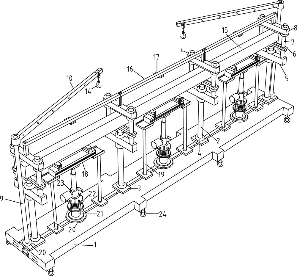
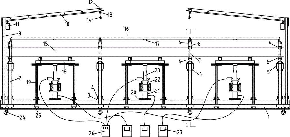
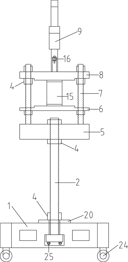
[0025] Embodiments of the present invention will be further described below in conjunction with the accompanying drawings.

[0026] see Figure 1-7, a multifunctional self-balancing continuous beam test reaction force loading frame, which includes a reaction force frame bottom plate 1, a Fuma wheel 24 is installed at the bottom of the reaction force frame bottom plate 1, and a longitudinal slide is processed on the middle part of the upper surface of the reaction force frame bottom plate 1 The chute is equipped with an electric lifting device 9, a counter force loading frame column 2 and a distribution beam support 19, and the counter force loading frame column 2 is processed with a full thread and is equipped with a directional wheel 25 at its bottom, and the top is threaded. The lower crossbeam 5 is installed, and the upper top surface of the lower crossbeam 5 is processed with a crossbeam column 7, and the middle beam 6 and the upper beam 8 are fixedly installed on the cros...


PUM


Abstract

The invention relates to a counterforce loading frame for a multifunctional self-balancing type continuous beam test. A longitudinal sliding groove is machined in the middle of the upper surface of a counterforce frame bottom plate. Electric hoisting devices, counterforce loading frame stand columns and distribution beam supports are arranged on the slide groove. Full threads are machined in the counterforce loading frame stand columns. Orientation wheels are arranged at the bottoms of the counterforce loading frame stand columns. Lower beams are arranged on the tops of the counterforce loading frame stand columns through screw thread fit. Middle beams and upper beams are fixedly arranged on beam stand columns through nuts. Test beams are arranged between the middle beams and the upper beams. Displacement monitoring device supports are arranged on the tops of the upper beams. Distribution beams are placed on the distribution beam supports. The two sides of the distribution beams are provided with rulers and slide grooves, wherein hooks are arranged on the slide grooves. Roller supports are located on the distribution beams. Jacks are arranged on the lower portions of the distribution beams. The counterforce loading frame is suitable for tests of continuous beams, simply supported beams and columnar components, and the span can be changed so that the counterforce loading frame can be used for components of different sizes.

Description

technical field [0001] The invention is a multi-functional self-balancing counter force loading frame for tests of continuous beams, simply supported beams, columns, etc., and belongs to the technical field of civil engineering test devices. Background technique [0002] In civil engineering tests, beam members are a type of test that often needs to be carried out. According to their mechanical characteristics, they can be divided into simply supported beams and continuous beams. At present, the experimental research on beam components mainly focuses on simply supported beams, while the research on continuous beams is relatively scarce. One of the important reasons is that simply supported beam tests are easy to operate and the test difficulty is low, while continuous beam tests using existing equipment However, it is more difficult, the preparation work before the test is complicated, the test accuracy is difficult to control, etc., and a relatively wide test site is requir...

Claims


Application Information

Patent Timeline
Patent Type & Authority Applications(China)
IPC IPC(8): G01N3/02
Inventor 徐港赵鹏王青唐广界赵娟江满
Owner CHINA THREE GORGES UNIV
Why Eureka
Try Eureka