Three-phase bridge PWM rectifier switching tube open-circuit fault diagnosis method

A rectifier switching tube, open-circuit fault technology, applied in instruments, measuring devices, measuring electricity and other directions, can solve the problems of complex algorithms, incomplete faults, faulty tube positioning errors, etc., and achieves high robustness and versatility.

Inactive Publication Date: 2015-12-16
NANJING UNIV OF AERONAUTICS & ASTRONAUTICS
View PDF3 Cites 36 Cited by
  • Summary
  • Abstract
  • Description
  • Claims
  • Application Information

AI Technical Summary

Problems solved by technology

The "per unit mean value method" uses the current PARK vector modulus length to normalize the three-phase current, simplifying the algorithm; by detecting the voltage diagnosis between the midpoint of the DC side and the midpoint of the AC side to eliminate the impact of the load mutation on the diagnosis, but it needs Add a voltage sensor
In addition, the above methods only consider the open-circuit failure mode of a single switch tube. When multiple tube failures occur, faulty tube positioning errors may occur or failures cannot be detected.
From the perspective of reliability, it is not comprehensive enough to study only single-tube open-circuit faults, and it is necessary to study the failure mode of multiple-tube open-circuit at the same time
Some schemes propose to use current phase angle derivatives for fault detection, which achieves good anti-false alarm ability for load mutations, and use normalized phase current average absolute value error for fault location, which can realize multi-tube fault detection, but the detection and Positioning is implemented in two steps, and the algorithm is complex
[0005] To sum up, the open-circuit fault diagnosis method of switching tubes of three-phase bridge PWM rectifiers given by the existing literature and patents can realize multi-tube open-circuit fault diagnosis, reduce There are still many shortcomings in the evaluation of small hardware costs, simple implementation algorithms, and high robustness to system transients.

Method used


Image

  • Three-phase bridge PWM rectifier switching tube open-circuit fault diagnosis method
  • Three-phase bridge PWM rectifier switching tube open-circuit fault diagnosis method
  • Three-phase bridge PWM rectifier switching tube open-circuit fault diagnosis method

Examples


Embodiment Construction

[0030] Combine below Attached picture Describe the technical solution of the invention in detail:

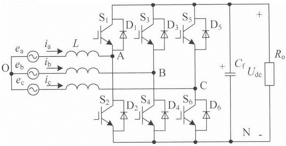
[0031] figure 1 It is a schematic diagram of the main circuit topology of the three-phase bridge PWM rectifier of the present invention picture . The first to sixth switching tubes S 1 ~S 6 is a, b, c three-phase bridge arm power tube, D 1 ~D 6 are the first to sixth freewheeling diodes, L is the three-phase filter inductor, C f is the DC side filter capacitor, R L is the DC load, e a 、e b 、e c is the three-phase grid voltage, i a i b i c is the three-phase grid side current, the reference direction as shown in the picture , U dc is the output voltage of the DC side, O is the midpoint of the AC side, and N is the negative pole of the DC side.

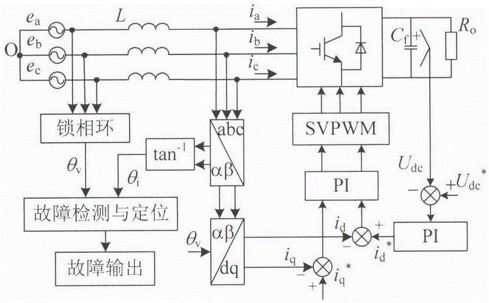
[0032] figure 2 It is the control frame of the three-phase bridge PWM rectifier system and its fault diagnosis method according to the present invention picture . The based system includes a three-phase PWM re...


PUM


Abstract

The invention discloses a three-phase bridge PWM rectifier switching tube open-circuit fault diagnosis method, and belongs to the field of a three-phase AC / DC converter. The invention aims to solve the problems of inaccurate, poor robustness and the like in multi-tube fault diagnosis in an existing diagnostic scheme. The method uses the characteristic that a fault phase grid-side current occurs to be a zero region when an open-circuit fault happens to any one of switching tubes in a three-phase bridge PWM rectifier, a current phase angle is extracted from a three-phase grid-side current, and fault detection and positioning are achieved according to the variation amount of the current phase angle and a power grid phase angle. The method disclosed by the invention can achieve effective diagnosis of open-circuit faults of both a single switching tube and a plurality of switching tubes in the three-phase bridge PWM rectifier, the software algorithm is simple, no additional hardware circuit is required, and the transient state of a system is highly robust.

Description

Technical field [0001] The present invention disclosed a method of opening and switching tube opening fault diagnosis for three -phase bridge PWM rectifier, which belongs to the field of three intersection DC transformations. Background technique [0002] Compared with the traditional non -controlling rectification or phase -control rectification scheme, the three -phase bridge PWM rectifier has the advantages of DC voltage controlled, realized unit power factor, network -side current harmonics, and energy can flow in both directions.Power occasions have been widely used.With the large -scale use of power converters, real -time and efficient diagnosis of its faults gradually become a research hotspot.The survey shows that about 38 % of the power transformation system failure is caused by the failure of the power switching device, which mainly includes short -circuit faults and open -road failures.For short -circuit faults, because it will instantly cause other normal components i...

Claims


Application Information

Patent Timeline
Patent Type & Authority Applications(China)
IPC IPC(8): G01R31/02
Inventor 许政肖岚宋佩云
Owner NANJING UNIV OF AERONAUTICS & ASTRONAUTICS
Why Eureka
Try Eureka