Axial line focusing spiral zone plate

An axial line and helical wave technology, applied in the field of diffractive optics, to achieve the effect of easy promotion and application, convenient design and production

Active Publication Date: 2015-12-16
LASER FUSION RES CENT CHINA ACAD OF ENG PHYSICS
View PDF3 Cites 22 Cited by
  • Summary
  • Abstract
  • Description
  • Claims
  • Application Information

AI Technical Summary

Problems solved by technology

However, for conventional focusing systems, there is a contradictory relationship between axial line focus and small focus spot, that is, a small focus spot requires a larger numerica

Method used


Image

  • Axial line focusing spiral zone plate
  • Axial line focusing spiral zone plate
  • Axial line focusing spiral zone plate

Examples


Embodiment Construction

[0028] In order to make the object, technical solution and advantages of the present invention more clear, the present invention will be further described in detail below in conjunction with the examples. It should be understood that the specific embodiments described here are only used to explain the present invention, not to limit the present invention.

[0029] The application principle of the present invention will be further described below in conjunction with the accompanying drawings and specific embodiments.

[0030] see Figure 1-Figure 6 :

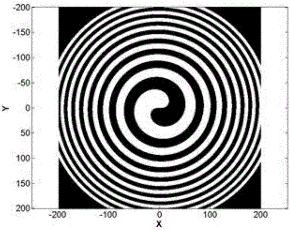
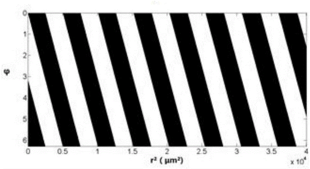
[0031] This embodiment discloses an axial line focusing helical zone plate suitable for soft X-ray transmission, refer to figure 1 and figure 2 ;

[0032] figure 1 Shown is a schematic structural diagram of the 50-period, p=1 axial line focusing helical zone plate of the present invention, in which the white filled helical annulus in the figure is the light-transmitting part, and the black area is the light-impermeable part...


PUM


Abstract

The invention discloses an axial line focusing spiral zone plate. The zone plate is formed by alternately arranging a series of discontinuous spiral light transmitting ring bands and light shielding ring bands. The coordinates of the spiral ring bands in different cycles are adjusted in a certain distributing mode, so that incident light passes through the ring bands in the different cycles to be focused at different focal points, and a hollow-column-shaped line focal point is formed. Compared with a common spiral zone plate with same numerical apertures, the size of the focal point on an optical axis is effectively lengthened; designing and manufacturing are convenient and rapid, and only a production formula of the spiral ring bands and focal distances corresponding to the cycles need to be designed according to requirements; practical application and practical popularization are easy, and particularly practical application to and practical popularization for the vacuum-ultraviolet-ray waveband to the soft-X-ray waveband are easy; the axial line focusing spiral zone plate has broad application prospects in the researching fields such as particulate control, extreme ultra-violet lithography, astronomy, microscopes and micro power systems.

Description

technical field [0001] The invention belongs to the field of diffractive optics, in particular to an axial line focusing helical zone plate. Background technique [0002] As an important branch of modern optics, singularity optics has developed rapidly in recent years. At the phase singularity, the phase of the optical wave field becomes indeterminate, and the amplitude of the field is zero. The optical vortex is a special light field, which has the characteristics of spiral wavefront and orbital angular momentum. There is a phase singularity in the center of the beam, and it has a dark hollow structure. It has become a hot research topic in the academic circle in recent years. Scholars at home and abroad have proposed methods such as geometric mode conversion, hologram, spiral phase plate / zone plate, liquid crystal spatial light modulation, etc. It shows attractive application prospects. In particular, in the field of X-rays, considering that the vortex beam as an optica...

Claims


Application Information

Patent Timeline
IPC IPC(8): G02B5/18
CPCG02B5/1876
Inventor 魏来范全平陈勇张强强晏卓阳杨祖华钱凤曹磊峰
Owner LASER FUSION RES CENT CHINA ACAD OF ENG PHYSICS
Why Eureka
Try Eureka