Novel magnetic card reading circuit structure

A circuit structure and circuit technology, applied in the direction of electromagnetic radiation induction, etc., can solve the problems of complex peripheral circuits, complex magnetic card reading circuit structures, and high costs, and achieve the effects of fewer peripheral devices, lower circuit costs, and simplified circuits.

Inactive Publication Date: 2015-12-16
石井国
View PDF0 Cites 1 Cited by
  • Summary
  • Abstract
  • Description
  • Claims
  • Application Information

AI Technical Summary

Problems solved by technology

At the same time, a voltage follower needs to be used to provide a reference voltage during the card reading process, so the circuit must be equipped with 4-gate operati

Method used


Image

  • Novel magnetic card reading circuit structure
  • Novel magnetic card reading circuit structure

Examples


Embodiment Construction

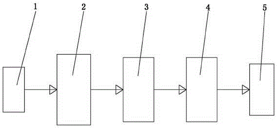
[0014] Such as figure 1 or figure 2 As shown, the application includes a read head 1, an amplification filter circuit 2, a delay circuit 3, a comparison shaping circuit 4 and a processor 5, the output end of the read head 1 is connected to the input end of the amplification filter circuit 2, and the amplification filter circuit 2 The output end of the delay circuit 3 is connected to the input end of the delay circuit 3, the output end of the delay circuit 3 is connected to the input end of the comparison shaping circuit 4, and the output end of the comparison shaping circuit 4 is connected to the processor 5.

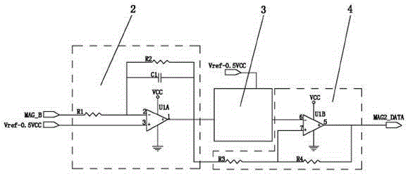
[0015] Such as figure 2 As shown, the amplification and filtering circuit 2 is composed of U1A, resistors R1 and R2, and capacitor C1.

[0016] The comparison shaping circuit 3 is composed of U1B, resistors R3 and R4.

[0017] This application uses a four-gate operational amplifier to read the weak triangular wave signals of two magnetic card tracks, and each track...


PUM


Abstract

The invention discloses a novel magnetic card reading circuit structure, which comprises a read head, an amplification filter circuit, a time delay circuit, a comparison and shaping circuit and a processor, an output end of the read head is connected with an input end of the amplification filter circuit; an output end of the amplification filter circuit is connected with an input end of the time delay circuit; an output end of the time delay circuit is connected with an input end of the comparison and shaping circuit; and an output end of the comparison and shaping circuit is connected with the processor. The novel magnetic card reading circuit structure has the advantages that by employing operational amplifiers as few as possible, amplification and shaping of a magnetic card reading signal are realized; a high-gain first-stage operational amplifier circuit or an automatic gain control (AGC) circuit is not required, and the amplification and shaping of magnetic card signals at different card speeds can be realized, so the cost of a circuit is greatly reduced, and the circuit is simplified; and the novel magnetic card reading circuit structure is low in cost, universal and small in quantity of peripheral circuits.

Description

technical field [0001] The application relates to a novel magnetic card reading circuit structure. Background technique [0002] In the existing magnetic card reading process, the weak triangular wave signals of the two tracks are read by the magnetic reading head, amplified and shaped into F2F square wave signals. In this process, the usual way to amplify and shape the magnetic card reading signal is to read the 20-30mV weak triangular wave signal of the swipe card, first through two stages of operational amplifiers, and then through a hysteresis comparator to achieve. At the same time, a voltage follower needs to be used to provide a reference voltage during the card reading process. In this way, a 4-gate operational amplifier circuit must be provided in the circuit, and the peripheral circuit is also very complicated. Therefore, the existing magnetic card reading circuit has complex structure and high cost. Contents of the invention [0003] In order to overcome the d...

Claims


Application Information

Patent Timeline
IPC IPC(8): G06K7/10
Inventor 石井国
Owner 石井国
Why Eureka
Try Eureka