A DC Grid Power Flow Controller Topology

A technology of power flow controller and DC power grid, applied in the direction of DC network circuit devices, electrical components, circuit devices, etc., can solve the problems of high technical difficulty and increased system operation loss, achieve small size, low withstand voltage requirements, and reduce costs Effect with running losses

Active Publication Date: 2017-12-08
INST OF ELECTRICAL ENG CHINESE ACAD OF SCI
View PDF5 Cites 0 Cited by
  • Summary
  • Abstract
  • Description
  • Claims
  • Application Information

AI Technical Summary

Problems solved by technology

The circuit structure mainly includes the energy-taking part and the commutation part. The energy-taking circuit takes energy from the DC system, uses modulation control to output the AC voltage waveform, and after the voltage is transformed by the transformer, the DC voltage is output through the three-phase six-pulse thyristor bridge for regulation. Branch power flow, this topology also requires the introduction of more power electronic devices, resulting in increased system operating losses
In addition, multiple IGBTs need to work in series in the DC energy harvesting system, which is technically difficult

Method used


Image

  • A DC Grid Power Flow Controller Topology
  • A DC Grid Power Flow Controller Topology
  • A DC Grid Power Flow Controller Topology

Examples


Embodiment 1

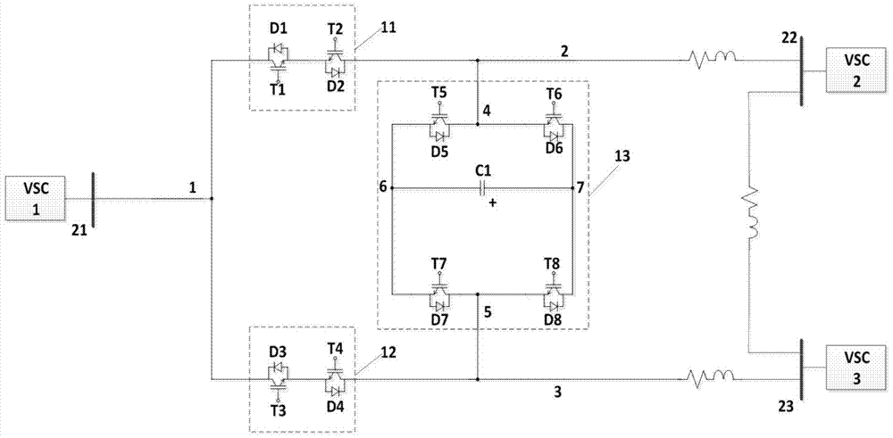
[0033] figure 2 Shown is the specific implementation of the DC grid power flow controller connected to the three-terminal DC ring network, wherein the first lead-out terminal 1 of the power flow controller is connected to the first converter station 21, and the second lead-out terminal 1 of the power flow controller The terminal 2 is connected to the second converter station 22 through the direct current transmission line, and the third lead-out terminal 3 of the power flow controller is connected to the third converter station 23 through the direct current transmission line.

Embodiment 2

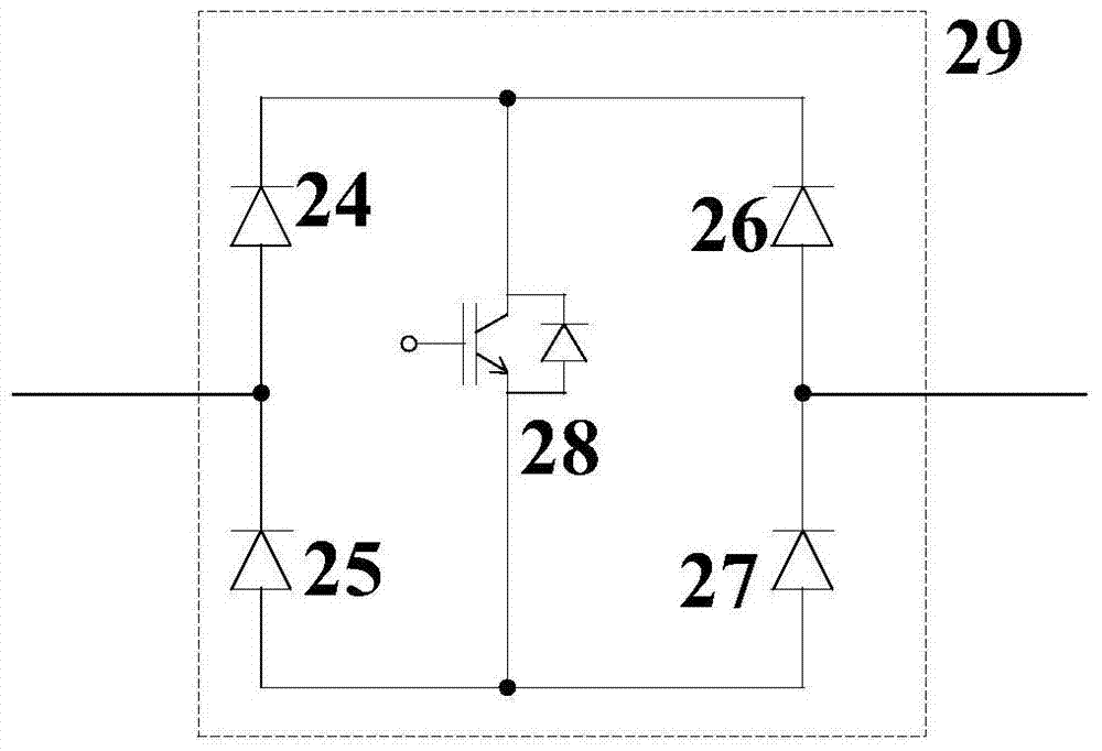
[0035] image 3 An alternative implementation of the guided switch module is shown. like image 3 As shown, the guide switch module is composed of four diodes 24 , 25 , 26 , 27 and a fully controlled device 28 . The cathode of the first diode 24 is connected with the cathode of the second diode 26, and is connected with the collector of the fully controlled device 28; the anode of the third diode 25 is connected with the anode of the fourth diode 27, And be connected with the emitter electrode of full control type device 28; The anode of the first diode 24 is connected with the cathode of the third diode 25, as the first lead-out terminal of guide switch; The anode of the second diode 26 is connected with the cathode of the third diode 25. The cathodes of the four diodes 27 are connected as the second lead-out terminal of the pilot switch.

Embodiment 3

[0037] Figure 4 Shown is another implementation of the power flow controller. like Figure 4 As shown, the full-bridge sub-modules are replaced by a full-bridge sub-module cascade structure 33 . The full-bridge sub-module cascade structure 33 is composed of a first full-bridge sub-module 31 and a second full-bridge sub-module 32 in cascade. The first lead-out terminal 34 of the second full-bridge sub-module 32 is connected to the second lead-out terminal 45 of the first full-bridge sub-module 31, and the second lead-out terminal of the first guide switch module 11 is connected to the second lead-out terminal of the first full-bridge sub-module 31. One lead-out terminal 44 is connected, the connection point is used as the second lead-out terminal 2 of the DC power flow controller, the second lead-out terminal of the second guide switch module 12 is connected to the second lead-out terminal 35 of the second full-bridge sub-module 32, The connection point serves as the third ...


PUM


Abstract

The invention discloses a DC power supply power flow controller topology, which is composed of a first guide switch module (11), a second guide switch module (12) and a full-bridge sub module (13), wherein the first leading-out terminal of the first guide switch module (11) is connected with the first leading-out terminal of the second guide switch module (12) to serve as a first leading-out terminal (1) of the DC power supply power flow controller; the second leading-out terminal of the first guide switch module (11) is connected with the first leading-out terminal (4) of the full-bridge sub module (13), and the connection point serves as a second leading-out terminal (2) of the DC power supply power flow controller; and the second leading-out terminal of the second guide switch module (12) is connected with the second leading-out terminal (5) of the full-bridge sub module (13) to serve as a third leading-out terminal (3) of the DC power supply power flow controller.

Description

technical field [0001] The invention relates to a DC grid power flow controller topology. Background technique [0002] With the shortage of traditional energy and the aggravation of environmental degradation, countries around the world have realized that the use and development of energy must transition from traditional energy to green renewable energy and other clean energy. In recent years, new energy technologies such as wind energy and solar energy have developed rapidly, but due to their intermittent and unstable characteristics, traditional technologies for accepting ultra-large-scale new energy are subject to more and more restrictions, and new technologies must be adopted , equipment and grid structure to meet the profound changes in the future energy pattern. The multi-terminal DC transmission system and DC grid technology based on conventional DC and flexible DC are one of the effective technical means to solve this problem. [0003] The DC power grid has three ...

Claims


Application Information

Patent Timeline
Patent Type & Authority Patents(China)
IPC IPC(8): H02J1/00
Inventor 朱晋何荣凯尹靖元韦统振
Owner INST OF ELECTRICAL ENG CHINESE ACAD OF SCI
Why Eureka
Try Eureka