Novel microgrid system, power balance control strategy and small-signal modeling method therefor

A micro-grid, a new type of technology, applied in the direction of reactive power adjustment/elimination/compensation, reactive power compensation, electrical digital data processing, etc. waves etc.

Inactive Publication Date: 2015-12-16
UNIV OF ELECTRONICS SCI & TECH OF CHINA
View PDF6 Cites 33 Cited by
  • Summary
  • Abstract
  • Description
  • Claims
  • Application Information

AI Technical Summary

Problems solved by technology

However, this method distorts the output voltage, increases harmonics in lines with inductive output impedance, and affects the measurement accuracy of output power
[0004] The above control methods are only effective for reactive power sharing under certain conditions, but the calculation process is relatively complicated, it is difficult to apply to engineering practice, and it is easy to affect the stability and power quality of the microgrid. The decomposition of the positive sequence and negative sequence components of each harmonic. Therefore, these control strategies are difficult to apply to the occasions where the impedance of each DG feeder line of the multi-converter microgrid is inconsistent and the microgrid has unbalanced and nonlinear loads. It is necessary to study A more accurate new layered control method that can be used to balance the reactive power and harmonic power of each DG in a multi-converter microgrid will be widely used in DG line impedance inconsistencies, microgrids with nonlinear loads, and complex engineering. application

Method used


Image

  • Novel microgrid system, power balance control strategy and small-signal modeling method therefor
  • Novel microgrid system, power balance control strategy and small-signal modeling method therefor
  • Novel microgrid system, power balance control strategy and small-signal modeling method therefor

Examples


Embodiment Construction

[0084] The technical solution of the present invention will be further described below in conjunction with the accompanying drawings.

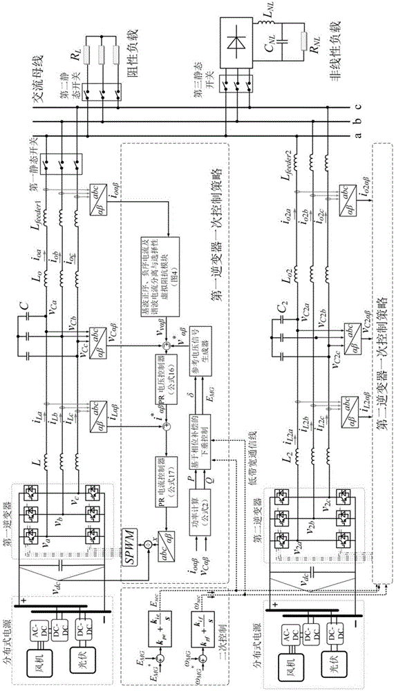
[0085] Such as figure 1 As shown, the new microgrid system includes two DG units connected in parallel to the AC bus, three-phase balanced resistive loads and nonlinear loads. The first DG unit includes the first distributed power supply and the first inverter connected in sequence , the first LCL type filter circuit, the first line impedance and the first static switch, and the primary strategy control module of the first inverter; the second DG unit includes the second distributed power supply, the second inverter, and the second distributed power supply connected in sequence Two LCL filter circuits, a second line impedance, and a primary strategy control module of the second inverter, the primary strategy control module of the first inverter and the primary strategy control module of the second inverter are respectively connected to the sec...


PUM


Abstract

The invention provides a novel microgrid system based on phase compensation and selective virtual impedance, a power balance control strategy and a small-signal modeling method therefor. The novel microgrid system comprises two paths of DG (distributed generation) units connected with an alternating current bus in parallel, a three-phase balance resistance load and a non-linear load; the DG unit comprises a distributed power supply, an inverter, an LCL type filter circuit, line impedance, two inverter primary strategy control modules and a secondary strategy control module that are connected in sequence; a first DG unit is connected with the alternating current bus through a first static switch; a second DG unit is connected with the alternating current bus through a second line impedance; and the three-phase balance resistance load and the non-linear load are connected with the alternating current bus through a second static switch and a third static switch separately. The invention provides a wattless and harmonic power balance control method for the novel microgrid system based on phase compensation droop control, selective virtual impedance and secondary control; and the wattless and harmonic power sharing of the microgrid under the nonlinear load can be effectively realized.

Description

technical field [0001] The invention belongs to the technical field of micro-grid control in power systems, and relates to a novel layered control strategy and small-signal modeling method for micro-grid reactive power and harmonic power balance, in particular to a droop control based on phase compensation, selectivity Novel microgrid system with virtual impedance and secondary control, its power balance control strategy and small signal modeling method. Background technique [0002] In recent years, distributed generation (Distributed Generation, DG) technology based on renewable energy has been widely used in modern power systems. DG units interfaced with inverters are usually installed in power distribution systems, so an effective control strategy for inverters is crucial to the operational stability and reliability of a parallel system with multiple distributed DG units. In the power distribution network, several DG units are gathered together to form a microgrid to su...

Claims


Application Information

Patent Timeline
Patent Type & Authority Applications(China)
IPC IPC(8): H02J3/18H02J3/01G06F19/00G06F17/50
CPCY02E40/30Y02E40/40Y02P80/14
Inventor 韩杨沈攀李红罗名煜李自鹏赵玉龙
Owner UNIV OF ELECTRONICS SCI & TECH OF CHINA
Why Eureka
Try Eureka